A

B

C

D

Text Solution
Verified by Experts
The correct Answer is:


Topper's Solved these Questions
SEMICONDUCTOR ELECTRONICS (MATERIAL, DEVICES AND SIMPLE CIRUITS )
AAKASH INSTITUTE ENGLISH|Exercise Assignment SECTION - D (Assertion & reason type Question)|10 VideosSEMICONDUCTOR ELECTRONICS (MATERIAL, DEVICES AND SIMPLE CIRUITS )
AAKASH INSTITUTE ENGLISH|Exercise Assignment section -B (Objective Type Question)|29 VideosRAY OPTICS AND OPTICAL INSTRUMENTS
AAKASH INSTITUTE ENGLISH|Exercise ASSIGNMENT (SECTION - D)|16 VideosSEMICONDUCTOR ELECTRONICS: MATERIALS, DEVICES AND SIMPLE CIRCUITS
AAKASH INSTITUTE ENGLISH|Exercise Assignment (Section-D (Assertion and reason))|5 Videos
Similar Questions
Explore conceptually related problems
AAKASH INSTITUTE ENGLISH-SEMICONDUCTOR ELECTRONICS (MATERIAL, DEVICES AND SIMPLE CIRUITS )-Assignment section -C (Previous years type question)
- In the energy band diagram of a material shown below, the open circles...
Text Solution
|
- A common emitter amplifier has a voltage gain of 50, an input impedanc...
Text Solution
|
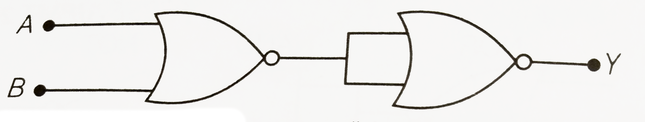
- In the following circuit, the output Y for all possible inputs A and B...
Text Solution
|
- For a cubic crystal structure which one of the following relation indi...
Text Solution
|
- A transistor is operated in common emitter configuration at constant c...
Text Solution
|
- A forward biased diode is
Text Solution
|
- The following figure shows a logic gate circuit with two inputs A and ...
Text Solution
|
- Application of forward bias to p-n junction
Text Solution
|
- Zener diode is used for:-
Text Solution
|
- Carbon, silicon and germanium have four valence electrons each. These ...
Text Solution
|
- Choose the false statement from the following.
Text Solution
|
- Copper has face-centered cubic (fcc) lattice with interatomic spacing ...
Text Solution
|
- The cations and anions are arranged n alternate form in:
Text Solution
|
- In semiconductors at a room temperature
Text Solution
|
- In good conductors of electricity the type of bonding that exist is
Text Solution
|
- In an insulator, the forbidden energy gap between the valence band and...
Text Solution
|
- In a p-n junction depletion region has a thickness of the order of
Text Solution
|
- Pure Si at 300 K has equal electron (n(e)) and hole (n(h)) concentrati...
Text Solution
|
- In a reverse biased p-n junction, when the applied bias voltages is eq...
Text Solution
|
- In the case of forward biasing of PN-junction, which one of the follow...
Text Solution
|