Home
Class 12
PHYSICS
In the following circuit, the output Y f...

In the following circuit, the output Y for all possible inputs A and B is expressed by the truth table

A

`{:(A,B,Y),(0,0,0),(0,1,0),(1,0,0),(1,1,1):}`

B

`{:(A,B,Y),(0,0,1),(0,1,1),(1,0,1),(1,1,0):}`

C

`{:(A,B,Y),(0,0,1),(0,1,0),(1,0,0),(1,1,0):}`

D

`{:(A,B,Y),(0,0,0),(0,1,1),(1,0,1),(1,1,1):}`

Text Solution

Verified by Experts

The correct Answer is:
D


`{:(A,B,Y),(0,0,0),(0,1,1),(1,0,1),(1,1,1):}`
Key idea: gates I and II are NOR gates. We can simplify the gate circuit as
Here gates-I and II are NOR gates the output (`A+B`) of gate-I will be appeared as input of gate-ii. The final output is
`Y=A+B=A+B`
This is the boolean expression of OR gate whose truth table is given below.
Promotional Banner

Topper's Solved these Questions

  • SEMICONDUCTORS

    RESONANCE ENGLISH|Exercise Exercise 2|16 Videos
  • REVISION DPP

    RESONANCE ENGLISH|Exercise All Questions|463 Videos
  • SIMPLE HARMONIC MOTION

    RESONANCE ENGLISH|Exercise Advanced Level Problems|13 Videos

Similar Questions

Explore conceptually related problems

For the logic circuit shown the truth table is

The following truth table corresponds to

The following figure shows a logic gate circuit with two inputs A and B and the output Y. The voltage waveforms of A,B and Y are as given : The logic gate is

The following figure shows a logic gate circuit with two inputs A and B and the output C. The voltage waveforms of A, B and C are as given The logic circuit is:

In the combination of the following gates the output Y can be written in terms of inputs A and B as

In the circuit below, A and B represents two inputs and C represents the output, the circuit represents. .

In the circuit below, A and B represent two inputs and C represents the output. The circuit represents

In the following digital circuit, what will be the output at ‘Z’, when the input (A,B) are (1,0) , (0,0), (1,1),(0,1) :

The Boolean expression of the output y in terms of the input A and B for the circuit shown in figure.

For inputs (A, B) and output(Y) of the following gate can be expressed as

RESONANCE ENGLISH-SEMICONDUCTORS-Exercise 3
  1. The radius of germanium (Ge) nuclide is measured to be twice the radiu...

    Text Solution

    |

  2. The energy gap of silicon is 1.14 eV . What is the maximum wavelength ...

    Text Solution

    |

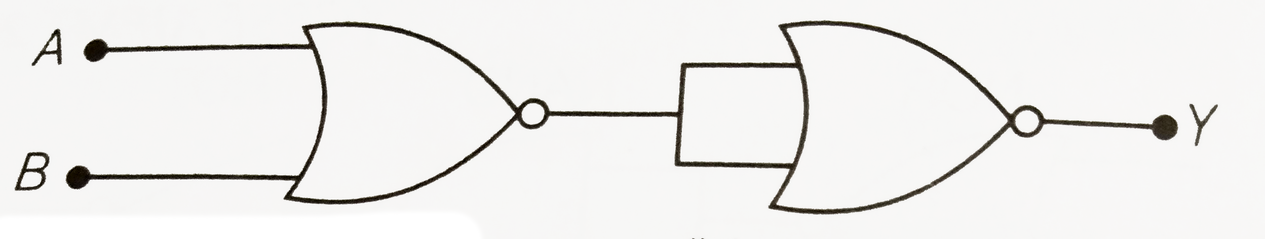
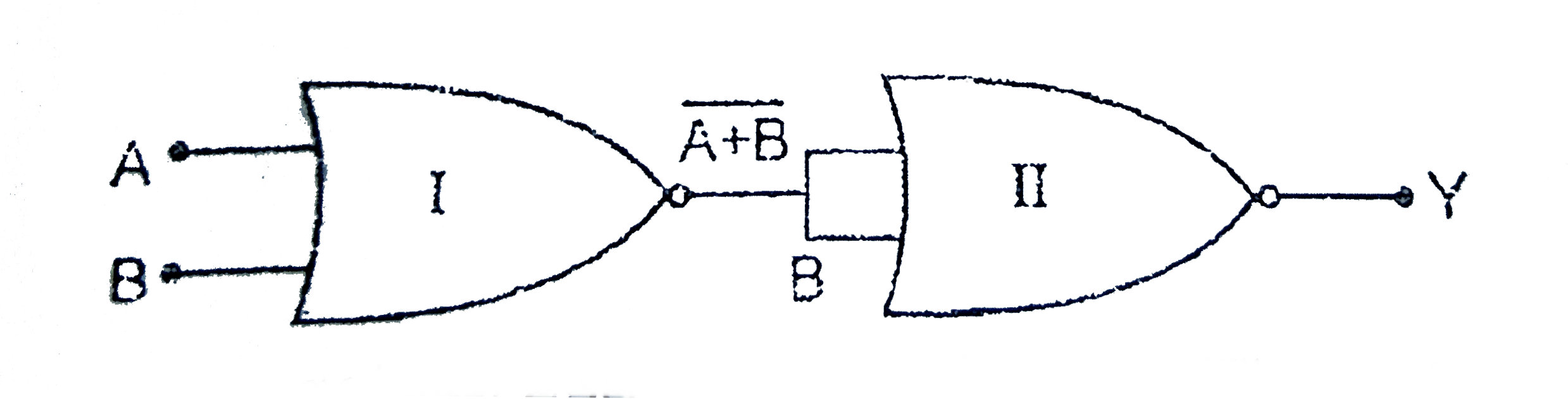
  3. In the following circuit, the output Y for all possible inputs A and B...

    Text Solution

    |

  4. In the energy band diagram of a material shown below, the open circles...

    Text Solution

    |

  5. A common emiiter amplifier has voltage gain 50 and current gain is 25....

    Text Solution

    |

  6. Draw the truth table for the logic gate arrangement shown in the figur...

    Text Solution

    |

  7. A p-n photodiode is made of a material with a band gap of 2.0 eV. The ...

    Text Solution

    |

  8. The circuit is equivalent to

    Text Solution

    |

  9. (a) For given transistor circuit, the base current is 10muA and the co...

    Text Solution

    |

  10. A p-n Photodiode is fabricated from a semiconductor with a band gap of...

    Text Solution

    |

  11. The symbolic representation of four logic gates (i) The logic sym...

    Text Solution

    |

  12. (a) Draw the circuit diagram of reversed bias p-n junction. (b). Dra...

    Text Solution

    |

  13. Which one of the following statement is false?

    Text Solution

    |

  14. The device that can act as a complete electronic circuit is

    Text Solution

    |

  15. A common emitter amplifier has a voltage gain of 50, an input impedanc...

    Text Solution

    |

  16. To get an output 1 from the circuit shown in figure the input must be ...

    Text Solution

    |

  17. In the following figure, the diodes which are forwards biased are :

    Text Solution

    |

  18. Pure Si at 500 K has equal number of electron (n(e)) and hole (n(h)) c...

    Text Solution

    |

  19. A zener diode having breakdown voltage equal to 15V, is used in a volt...

    Text Solution

    |

  20. A transistor is operated in common-emitter configuration at V(c) = 2 v...

    Text Solution

    |