Home
Class 12
PHYSICS
The circuit is equivalent to...

The circuit is equivalent to

A

AND gate

B

NAND gate

C

NOR gate

D

OR gate

Text Solution

Verified by Experts

The correct Answer is:
C

The gate circuit can be shown by giving two inputs A and B.

Output of NOR gate `Y_(1)=overline(A+B)`
Output NAND gate, `Y_(2)=overline(Y_(1).Y_(2))`
`=overline(Y_(1))+overline(Y_(1))`
`=overlineoverline(A+B)+overlineoverline(A+B)`
`=(A+B)+(A+B)`
`=A+B`
Out of NOT gate `Y=overline(Y_(2))`
`=overline(A+B)`
Which is the output of NOR gate. Alternative:

`{:(" ""NOR",,"NAND",,"NOT",),("A B Y"_(1),Y_(1),Y_(1),Y_(2),Y,),("0 0 1",1,1,0,1,),("0 1 0",0,0,1,0,),("1 0 0",0,0,1,0,),("1 1 0",0,0,1,0,):}`
Same as NOR gate
`{:(" ""NOR Gate"),("0 0 1"),("0 1 0"),("1 0 0"),("1 1 0"):}`.
Promotional Banner

Topper's Solved these Questions

  • SEMICONDUCTORS

    RESONANCE ENGLISH|Exercise Exercise 2|16 Videos
  • REVISION DPP

    RESONANCE ENGLISH|Exercise All Questions|463 Videos
  • SIMPLE HARMONIC MOTION

    RESONANCE ENGLISH|Exercise Advanced Level Problems|13 Videos

Similar Questions

Explore conceptually related problems

Following circuit is equivalent to

The circuit as shown in the figure is equivalent to

Passage : From the above circuit, the equivalent emf between the terminals A and B is

Five equal resistance each of value R are connected in a circuit . Find equivalent resistance of the network between points A and C

Passage : From the above circuit, equivalent internal resistance of the combination is

The logic gate equivalent to the given logic circuit is :

For the following circuit the equivalent capacitance P and Q is

The circuit given in figure, is equivalent to

Given the circuit : Which of the following is equivalent to the above circuit ? The true statement in the above is/are

Consider the shown circuit. The capacitor is uncharged when the swith is closed at time t=0. Which of the circuit given in option is equivalent to the shown circuit as t approaches infinity?

RESONANCE ENGLISH-SEMICONDUCTORS-Exercise 3
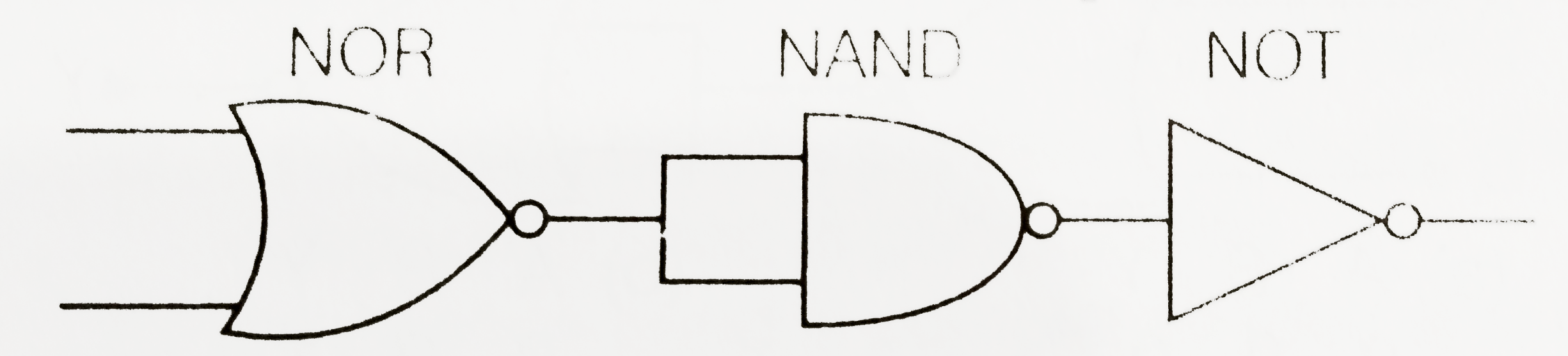
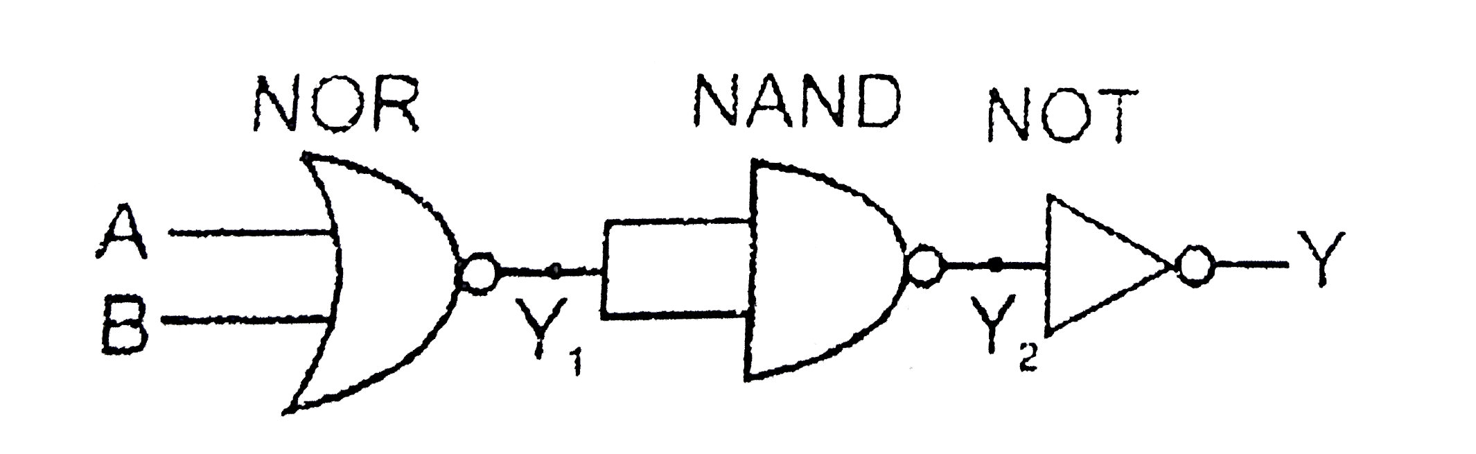
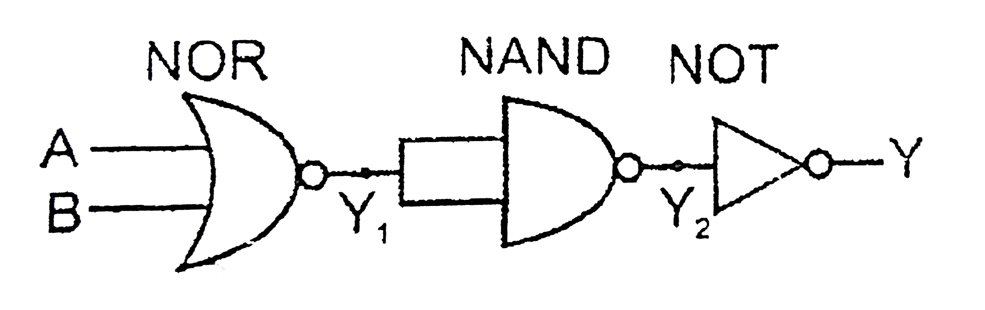
  1. Draw the truth table for the logic gate arrangement shown in the figur...

    Text Solution

    |

  2. A p-n photodiode is made of a material with a band gap of 2.0 eV. The ...

    Text Solution

    |

  3. The circuit is equivalent to

    Text Solution

    |

  4. (a) For given transistor circuit, the base current is 10muA and the co...

    Text Solution

    |

  5. A p-n Photodiode is fabricated from a semiconductor with a band gap of...

    Text Solution

    |

  6. The symbolic representation of four logic gates (i) The logic sym...

    Text Solution

    |

  7. (a) Draw the circuit diagram of reversed bias p-n junction. (b). Dra...

    Text Solution

    |

  8. Which one of the following statement is false?

    Text Solution

    |

  9. The device that can act as a complete electronic circuit is

    Text Solution

    |

  10. A common emitter amplifier has a voltage gain of 50, an input impedanc...

    Text Solution

    |

  11. To get an output 1 from the circuit shown in figure the input must be ...

    Text Solution

    |

  12. In the following figure, the diodes which are forwards biased are :

    Text Solution

    |

  13. Pure Si at 500 K has equal number of electron (n(e)) and hole (n(h)) c...

    Text Solution

    |

  14. A zener diode having breakdown voltage equal to 15V, is used in a volt...

    Text Solution

    |

  15. A transistor is operated in common-emitter configuration at V(c) = 2 v...

    Text Solution

    |

  16. In forward biasing of the p-n junction

    Text Solution

    |

  17. If a small amount of antimony is added to germanium crystal

    Text Solution

    |

  18. Value of forbidden energy gap for semi conductor is:

    Text Solution

    |

  19. Ga As is a/an:

    Text Solution

    |

  20. The number of free electrons is Si at normal temperature is

    Text Solution

    |