Home
Class 12
PHYSICS
Figure shows a wire frame PQSTXYZ placed...

Figure shows a wire frame `PQSTXYZ` placed in a time varying magnetic field given as `B=betat`, where `beta` is a positive constant.Resistance per unit length of the wire is `lambda`.Find the current induced in the wire and draw its electrical equivalent diagram.

Text Solution

Verified by Experts

Induced `emf` in part `PQST=beta a^(2)` (in anticlockwise direction, from Lenz's Law)
Similarly Induced `emf` in part `TXYZ=beta b^(2)` (in anticlockwise direction, from Lenz's Law)
Total resistance of the part `PQST=lambda4a`
Total resistance of the part `TXYZ=lambda4b`.The equivalent circuit is as shown in th following diagram.
Writing `KVL` along the current flow
`betab^(2)-betaa^(2)-lambda4ai-lambda4bi=0`
`i=beta/(4lambda)(b-a)`
Promotional Banner

Topper's Solved these Questions

  • ELECTROMAGNETIC INDUCTION

    RESONANCE ENGLISH|Exercise Problem|12 Videos
  • ELECTROMAGNETIC INDUCTION

    RESONANCE ENGLISH|Exercise Exercis-1|63 Videos
  • ELECTRODYNAMICS

    RESONANCE ENGLISH|Exercise Advanced level problems|31 Videos
  • ELECTROSTATICS

    RESONANCE ENGLISH|Exercise HLP|40 Videos

Similar Questions

Explore conceptually related problems

Calculate force per unit length acting on the wire B due to the current flowing in the wire A. (see figure below)

The figure shows a wire frame in xy-plane carryigna current I . The magnetic field at the point O is

Figure 3.15(a) shown two circular rings of radii a and b (a gt b) joined together with wires of negligible resistance. Figure 3.15(b) shown thew pattern obtained by folding the small loop in the plane of the large loop. (a) The pattern shown in Fig.3.15( c ) is obtained by twisting the small loop of Fig.3.15(a) through 180^(@) . All the three arrangement are placed in a uniform time varying magnetic field dB//dt = k , perpendicular to the plane of the loops. if the resistance per unit length of the wire is lambda , then determine the induced current in each case.

The resistance per unit length of the wires in segments AB, BC, CD, and AD are the same. The magnetic field due to the current at point O is

Figure shows two circular rings of radii a & b (a gt b) joined together by wire of negligible resistance. If the arrangement is placed in a time varying magnetic field, (dB)/(dt)=k and if the resistance per unit length of wire is lambda , then induced current is

A short-circuited coil is placed in a time-varying magnetic field. Electrical power is dissipated due to the current induced in the coil. If the number of turns were to be quadrupled and the wire radius halved, the electrical power dissipated would be

A conducting wire frame is placed in a magnetic field which is directed into the paper. The magnetic field is increasing at a constant rate. The directions of induced currents in wires AB and CD are

A wire is bent in the form of a square of side la in a varying magnetic field B= prop B_(0)t hatk . If the resistance per unit length is lambda . then find the following: (i) The direction of induced current (ii) The current in the loop (iii) Potential difference between P and Q

A conducting wire frame is placed in a magnetic field which is directed into the paper. The magnetic field is increasing at a constant rate. The direction of induced current in wire AB and CD are

A wire is bent in the form of a square of side a in a varying magnetic field vec(B)= prop B_(0) t hat(k) . If the resistance per unit length is lamda , then find the following (i) The direction of induced current (ii) The current in the loop (iii) Potential difference between P and Q

RESONANCE ENGLISH-ELECTROMAGNETIC INDUCTION-A.l.P
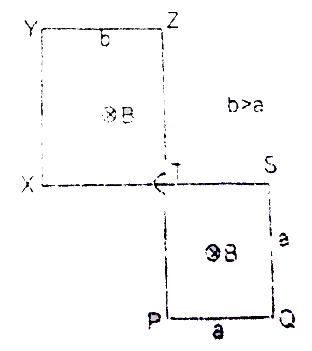
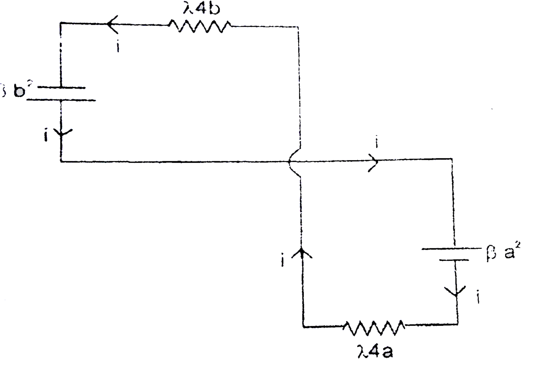
  1. Figure shows a wire frame PQSTXYZ placed in a time varying magnetic fi...

    Text Solution

    |

  2. A long thin wire carrying a varying current I = i(0) sin omegat lies a...

    Text Solution

    |

  3. In the figure shown a conducting rod of length l, resistnace R and mas...

    Text Solution

    |

  4. Figure shows a conducting rod of length l = 10 cm, resistance R and ma...

    Text Solution

    |

  5. In the figure, a conducting rod of length l=1 meter and mass m = 1 kg ...

    Text Solution

    |

  6. A conducting frame abcd is kept in a vertical plane. A conducting rod ...

    Text Solution

    |

  7. L is a smooth conducting loop of radius l=1.0 m & fixed in a horizonta...

    Text Solution

    |

  8. Two capacitors of capacitances 2C and C are connected in series with a...

    Text Solution

    |

  9. In the figure shown PQRS is a fixed resistanceless conducting frame in...

    Text Solution

    |

  10. the linear charge density of a thin metallic rod varies with the dista...

    Text Solution

    |

  11. In the figure shown a long conductor carries constant current I. A rod...

    Text Solution

    |

  12. An infinitesimally small bar magnet of dipole moment M is moving with ...

    Text Solution

    |

  13. ABCEFGA is a square conducting frame of side 2 m and resistance 1 Omeg...

    Text Solution

    |

  14. A square loop of side 12 cm with its sides parallel to X and Y axes is...

    Text Solution

    |

  15. In the circuit shown, the switch S is shifted to position 2 from posit...

    Text Solution

    |

  16. A square loop ABCD of side l is moving the xy plane with velocity vecv...

    Text Solution

    |

  17. The wire loop shown in the figure lies in uniform magnetic induction B...

    Text Solution

    |

  18. A metallic coil of N turns of radius r, resistance R, and inductance L...

    Text Solution

    |

  19. A telescope has an objective lens of focal length 150 cm and an eyepie...

    Text Solution

    |

  20. A long cylinder of radius a carrying a uniform surface charge rot...

    Text Solution

    |