Home
Class 12
PHYSICS
In the figure shown , after the switch ...

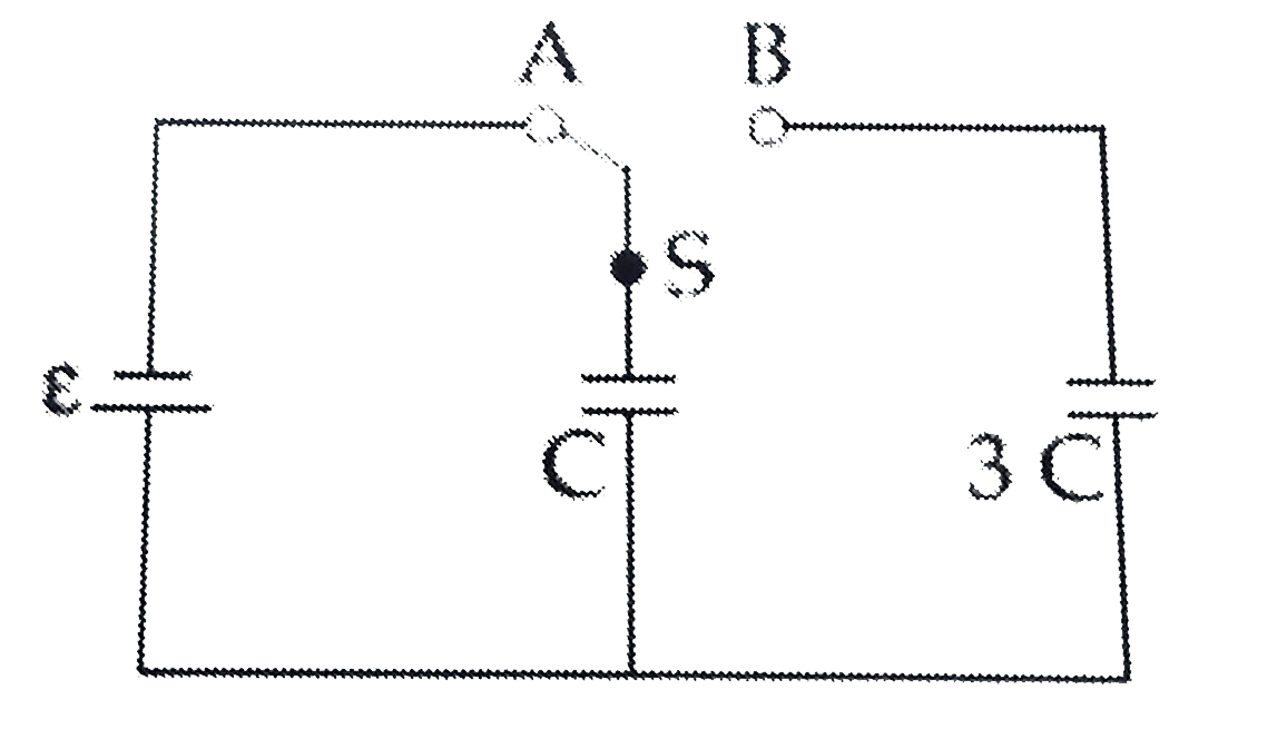
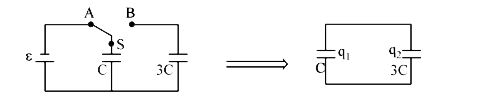
In the figure shown , after the switch 's' is turned from postion 'A' to postion 'B' the energy dissipated in the circuit in terms of capactance 'C' and total charge 'Q' is :

Text Solution

Verified by Experts

The correct Answer is:
8

`q_(1)+q_(2)=CE rArr q_(1)=(CE)/(4)rArr q_(2)=(3CE)/(4)`
`(q_1)/( C) =(q_(2))/(3C)`

initial energy `=(CE^2)/(2)`
Final energy `=(q_(1)^(2))/(2C)+(q_(2)^(2))/(2xx3C)`
`=(C^2E^2)/(32)+(9C^2E^2)/(32xx3)=(4CE^2)/(32)`
`H=Detal U =(CE^2)/(2)-(CE^2)/(8)=(3CE^2)/(8)` .
Promotional Banner

Topper's Solved these Questions

  • JEE MAIN REVISION TEST 8 (2020)

    VMC MODULES ENGLISH|Exercise PHYSICS (SECTION 2)|5 Videos
  • JEE MAIN REVISION TEST 5 (2020)

    VMC MODULES ENGLISH|Exercise PHYSICS (SECTION 2)|5 Videos
  • JEE MAIN REVISION TEST- 16

    VMC MODULES ENGLISH|Exercise PHYSICS (SECTION 2)|5 Videos

Similar Questions

Explore conceptually related problems

A capacitor of 2 muF is charged as shown in the figure. When the switch S is turned to position 2, the percentage of its stored energy dissipated is

In the circuit as shown in the figure, switch S is added at t=0. Then:

In the circuit shown in the figure, the switch S is in position 1 for a long time. Now the switch is thrown to position 2. Find the total heat developed in the circuit till the steady state is reached again.

A capacitor of 2 mu F is charged as shown in the diagram. When the switch S is turned to position 2, the percentage of its stored energy dissipated is:

In the circuit shown in figure the switch S is closed at t = 0. A long time after closing the switch

In the circuit shown in figure switch S is thrown to position 1 at t=0 . when the current in the resistort is 1A , it is shifted to position 2. the total heat generated in the circuit after shifting to position 2 is

In the circuit shown in figure switch S can be shift to position A or position B. Current though resistance is say i_(1) when switch is in position. A and when switch is in position B, then

In the circuit shown in figure switch S is closed at time t=0 Current I from the battery at time t is given by

In the circuit shown in fig, if the switch S is closed at t = 0 , the capacitor charges with a time constant

In the circuit shown in the figure, switch S is closed at time t=0 . Select the correct statements.