Text Solution
Verified by Experts


Topper's Solved these Questions
DC CIRCUIT
VMC MODULES ENGLISH|Exercise LEVEL-0 LONG ANSWER TYPE|3 VideosDC CIRCUIT
VMC MODULES ENGLISH|Exercise LEVEL-1 DAILY TUTORIAL SHEET-1|15 VideosDC CIRCUIT
VMC MODULES ENGLISH|Exercise LEVEL-0 SHORT ANSWER TYPE|9 VideosCURRENT ELECTRICITY
VMC MODULES ENGLISH|Exercise IN-CHAPTER EXERCISE-F|10 VideosDYNAMICS OF A PARTICLE
VMC MODULES ENGLISH|Exercise JEE Advance (Archive) Level - II (SINGLE OPTION CORRECT TYPE )|31 Videos
Similar Questions
Explore conceptually related problems
VMC MODULES ENGLISH-DC CIRCUIT-LEVEL-0 SA-II: Short Answer Type - II
- When is more power delivered to a light bulb, just after it is turned ...
Text Solution
|
- What will be the value of current through the 2Omega resistance for t...
Text Solution
|
- Two students X and Y perform an experiment on potentiometer separating...
Text Solution
|
- The circuit shownin Fig. 7.33 contains a battery , a rheostat , and tw...
Text Solution
|
- The element of heater is very hot while the wires carrying current are...
Text Solution
|
- What is the amount of work done in bringing a mass from the surface of...
Text Solution
|
- Calculate the value of the current drawn from a 5V battery in the circ...
Text Solution
|
- (i) Calcuate the equivalent resistance of the given electronical netwo...
Text Solution
|
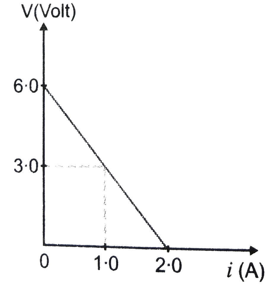
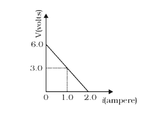
- The following graph shows the variation of terminal potential differen...
Text Solution
|
- In order to increase the resistance of a given wire of uniform cross s...
Text Solution
|
- Define resistivity of a conductor. Plot a graph showing the variation ...
Text Solution
|
- Two students ‘X’ and ‘Y’ perform an experiment on potentiometer separa...
Text Solution
|