A
B
C
D
Text Solution
Verified by Experts
The correct Answer is:


Topper's Solved these Questions
Similar Questions
Explore conceptually related problems
VMC MODULES ENGLISH-MOCK TEST 9-PHYSICS (SECTION 2)
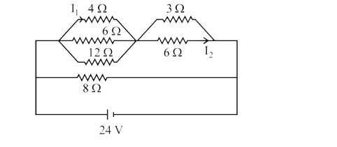
- In the circuit shown in fig., the value of I1+I2 is
Text Solution
|
- A carnot engine operates with source at 127^(@)C and sink at 27^(@)C. ...
Text Solution
|
- A non-isotropic solid metal cube has coefficients of linear expansion ...
Text Solution
|
- A particle (m = 2 kg) slides down a smooth track AOC starting from res...
Text Solution
|
- A loop ABCA of straight edges has three corner points A (8, 0, 0), B (...
Text Solution
|
- A beam of electromagnetic radiation comprised of wavelength 620 nm on ...
Text Solution
|