A
B
C
D
Text Solution
Verified by Experts
The correct Answer is:


Topper's Solved these Questions
Similar Questions
Explore conceptually related problems
VMC MODULES ENGLISH-MOCK TEST 6-PHYSICS (SECTION 2)
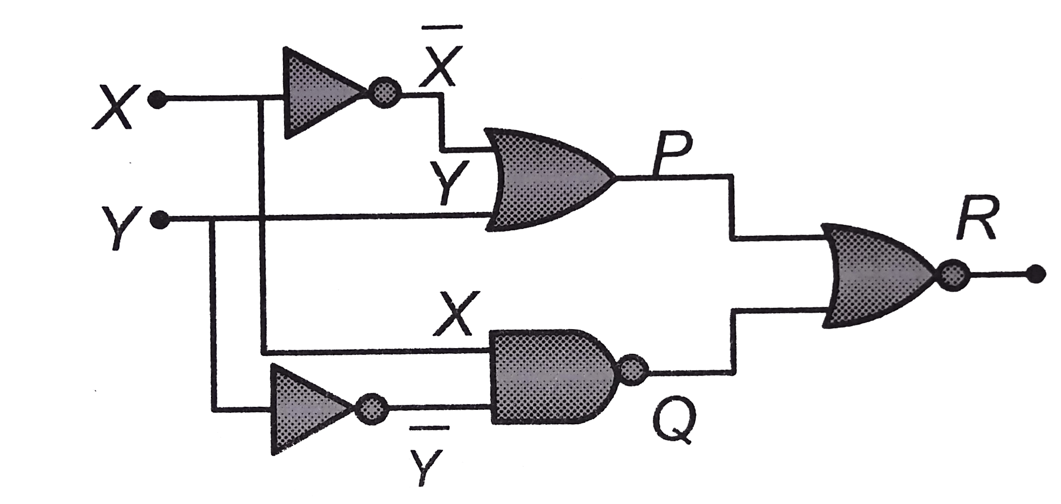
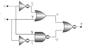
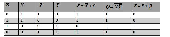
- Figure gives a system of logic gates. From the study of truth table it...
Text Solution
|
- Three containers C(1), C(2) and C(3) have water at different temperatu...
Text Solution
|
- A ball is dropped from the top of a tower. In the last second of motio...
Text Solution
|
- Ratio of the wavelengths of first line of Lyman series and first line ...
Text Solution
|
- A rocket of mass M is launched vertically from the surface of the eart...
Text Solution
|
- The series combination of two batteries, both of the same emf 20 V, bu...
Text Solution
|