A
B
C
D
Text Solution
Verified by Experts
The correct Answer is:


Topper's Solved these Questions
CURRENT ELECTRICITY
PHYSICS WALLAH|Exercise NEET Past 5 Years Questions|23 VideosCURRENT ELECTRICITY
PHYSICS WALLAH|Exercise NEET Past 5 Years Questions|23 VideosALTERNATING CURRENT
PHYSICS WALLAH|Exercise NEET PAST 5 YEARS QUESTIONS |8 VideosDUAL NATURE OF RADIATION AND MATTER
PHYSICS WALLAH|Exercise Neet past 5 years questions|16 Videos
Similar Questions
Explore conceptually related problems
PHYSICS WALLAH-CURRENT ELECTRICITY-Level-2
- A wire of resistance R is elongated n-fold to make a new uniform wire....
Text Solution
|
- A 10 m long wire ofresistance 20 Omega is connected in series with bat...
Text Solution
|
- The effective resistance across the point A & B is
Text Solution
|
- A battery having e.m.f. 5 V and internal resistance 0.5 Omega is conne...
Text Solution
|
- A cell of e.mf. E and internal resistance r is connected in series wit...
Text Solution
|
- In a ammeter 0.2% of main current passes through the galvanometer. If ...
Text Solution
|
- Three voltmeters A, B and C having resistances R, 1.5 R and 3 R respec...
Text Solution
|
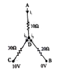
- In the circuit shown, the ratio (I(1))/(I(2)) is equal to
Text Solution
|
- A resistance wire has a resistance R. Half of this wire is stretched t...
Text Solution
|
- Consider the figure, cross-sectional area of consider at A and B is 2...
Text Solution
|
- The time constant of the circuit shown in the figure is
Text Solution
|
- A part of a circuit is shown in figure V(R)-V(C ) is equal to 12 V. I(...
Text Solution
|
- Two identical calls send the same current in 2 Omega resistance, wheth...
Text Solution
|
- The potentiometer wire AB shown in figure is 50cm long.When AD=30cm, n...
Text Solution
|
- A and B are two points on a uniform ring of resistance 15Omega. The lt...
Text Solution
|
- Four resistors are connected as shown in the figure. A 6 V battery of ...
Text Solution
|
- Two electric bulbs whose resistances are in the ratio of 1:2 are conne...
Text Solution
|
- The charge flowing through a resistance R varies with time t as Q = at...
Text Solution
|
- Equivalent resistance between O and circumference (If resistance of ci...
Text Solution
|
- A 5-A wire can withstand a maximum power of 1W in circuit. The resista...
Text Solution
|