Home
Class 12
PHYSICS
In the shown arrangement of the experime...

In the shown arrangement of the experiment of the meter bridge if AC corresponding to null deflection of galvanometer is x. what would b e its value if the radius of the wire AB is doubled:-

A

Statement-1 is true, Statement-2 is false

B

Statement-1 is true, Statement-2 is true, Statement-2 is the correct explanation of Statement-1

C

Statement-1 is true, Statement-2 is true, Statement-2 is not the correct explanation of Statement-1

D

Statement-1 is false, Statement-2 is true

Text Solution

Verified by Experts

The correct Answer is:
B
Promotional Banner

Topper's Solved these Questions

  • CURRENT ELECTRICITY

    ALLEN|Exercise EX.II|66 Videos
  • CURRENT ELECTRICITY

    ALLEN|Exercise EXERCISE-V A|20 Videos
  • CIRCULAR MOTION

    ALLEN|Exercise EXERCISE (J-A)|6 Videos
  • GEOMETRICAL OPTICS

    ALLEN|Exercise subjective|14 Videos

Similar Questions

Explore conceptually related problems

In the shown arrangement of the experiment of the meter bridge if AC corresponding to null deflection of galvanometer is x, what would be its value if the radius of the wire AB is doubled?

In the shows arrangement of a meter bridge, if AC corresponding to null deflection of galvanometer is x, what would be its value if the radius of the wire AB is doubled?

Statement I: In the meter bridge experiment shown in figure, the balance length AC corresponding to null deflection of the galvanometer is x. If the radius of the wire AB is doubled, the balanced length becomes 4x. Statement II: The resistance of a wire is inversely proportional to the square of its radius.

STATEMENT-1 : In the meter bridge experimeter shown in figure the balance length AC corresponding to null deflection of the galvanometer is x. If the radius of the wire AB is doubled, the balance length becomes 4x. and STATEMENT-2 : The resistance of a wire a inversely proportional to the square of its radius.

Shown in the figure below is a meter- bridge set up will null deflection in the galvanometer. The value of the unknown resistor R is

A meter bridge setup is shown in the figure. If there is null deflection in galvanometer when length AC = 20 cm, then the value of resistance R is

A nichrome wire AB, 100 cm long and of uniform cross section cross section is mounted on a meter scale the points A and B coinciding with 0 cm and 100 cm marks respectively. The wire has a resistance S = 50 ohm, Ay point C along this wire, between A and B is called a variable point to which on end of and electrical element is commeted. In the following questions this arrangement will be referred to as 'wire AB'. In the circuit adjacent arrangement it is found that deflection in the galvanometer is 10 divisions. Also the voltage across the 'wire AB' is equal to the across the galvanometer. the current sensitivity of the galvanometer is about.

A straight segment OC (of length L meter) of a circuit carrying a current I amp is placed along the x- axis ( fig.). Two infinetely long straight wires A and B , each extending from z = -oo to +oo , are fixed at y = -a meter and y = +a meter respectively, as shown in the figure. If the wires A and B each carry a current I amp into the plane of the paper, obtain the expression for the force acting on the segment OC . What will be the force on OC if the current in the wire B is reversed?

Consider the potentiometer circuit arranged as in figure. The potentiometer wire is 600cm long. At what distance from the point A should the jockey touch the wire to get zero deflection in the galvanometer? b) If the jockey touches the wire at a distance of 560cm from A, What will be the current in the galvanometer?

While doing an experiment with potentiometer (see figure) it was found that the deflection is one sided and (i) the deflection decreased while moving from one and A of the wire, to the end R, (ii) the deflection increased, while the jockey was moved towards the end D. (a)Which terminal positive and negative of the cell E_1 is connected at X in case (i) and how is E_1 related to E ? (b)Which terminal of the cell E_1 is connected at X in case (i in a) ?

ALLEN-CURRENT ELECTRICITY-EXERCISE-V B
  1. Which of the following is // are correct about electric current ?

    Text Solution

    |

  2. To the potentiometer wire of L and 10Omega resistance, a battery of em...

    Text Solution

    |

  3. A wire of resistance 12Omegam^(-1) is bent to form a complete circle o...

    Text Solution

    |

  4. See the electricall circuit shown in this figure. Which of the followi...

    Text Solution

    |

  5. A galvanometer having a coil resistance of 60 Omega shows full scale ...

    Text Solution

    |

  6. A student measures the terminal potential difference (V) of a cell (of...

    Text Solution

    |

  7. If an electron revolves in the circular path of radius 0.5A^(@) at a f...

    Text Solution

    |

  8. The external diameter of a 314 m long copper tube is 1.2 cm and the i...

    Text Solution

    |

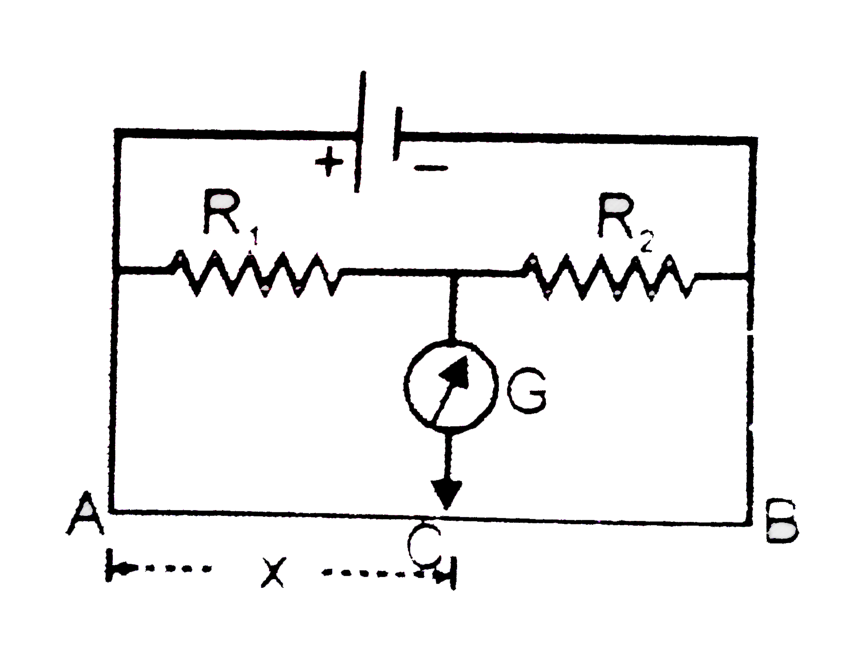
  9. In the shown arrangement of the experiment of the meter bridge if AC c...

    Text Solution

    |

  10. A potentiometer circuit is set up as shown. The potential gradient acr...

    Text Solution

    |

  11. A galvanometer has a coil of resistance 100 Omega and gives full scale...

    Text Solution

    |

  12. Consider the following two statements. A. Kirchhoff's junction law f...

    Text Solution

    |

  13. For a the current loops shown in the figu re, kirchhoff's loop rule f...

    Text Solution

    |

  14. In a potentiometer arrangement, a cell of emf 1.25 V gives a balance p...

    Text Solution

    |

  15. A current of 2 A flows through a 2Omega resistor when connected acros...

    Text Solution

    |

  16. If power dissipated in the 9Omega resistor in the circuit shown is 36 ...

    Text Solution

    |

  17. In the circuit shown in the figure, if potential at point A is taken t...

    Text Solution

    |

  18. A galvanometer of resistance, G, is shunted by a resistance S ohm. To ...

    Text Solution

    |

  19. A thermocouple of negligible resistance produces an e.m.f. of 40mu (V)...

    Text Solution

    |

  20. Figure shows three resistor configurations R1,R2 and R3 connected to 3...

    Text Solution

    |