Text Solution
Verified by Experts


Topper's Solved these Questions
SEMICONDUCTOR DEVICES
AAKASH SERIES|Exercise Problems (LEVEL-II)|9 VideosSEMICONDUCTOR DEVICES
AAKASH SERIES|Exercise EXAMPLES|56 VideosSEMICONDUCTOR DEVICES
AAKASH SERIES|Exercise Exercise (very Short answer questions)|36 VideosRAY OPTICS
AAKASH SERIES|Exercise PROBLEMS ( LEVEL-II)|60 VideosUNITS AND MEASUREMENT
AAKASH SERIES|Exercise PRACTICE EXERCISE|45 Videos
Similar Questions
Explore conceptually related problems
AAKASH SERIES-SEMICONDUCTOR DEVICES-Problems (LEVEL-I)
- A potential barrier of 0.3V exists across a P-N junction (a) If the de...
Text Solution
|
- A junction diode is connected to an external resistance of 100Omega an...
Text Solution
|
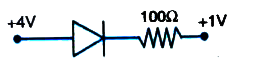
- The junction diode shown in figure is ideal. Find the current in the c...
Text Solution
|
- Determine the current through a silicon diode of (barrier potential = ...
Text Solution
|
- Find the current in the circuit shown below
Text Solution
|
- Calculate the current flowing in the circuit below which has two oppos...
Text Solution
|
- The circuit shown in figure contains two diodes each with a forward re...
Text Solution
|
- A p-n junction diode can withstand current up to 10 mA under forward b...
Text Solution
|
- The resistance of the diode in the forward biased condition is 20Omega...
Text Solution
|
- Find maximum voltage across AB in the circuit shown in figure. Assume ...
Text Solution
|
- The diode used in the circuit shown in the figure has a constant volta...
Text Solution
|
- For the circuit shown in Fig. find 1) the output voltage 2) the vo...
Text Solution
|
- The applied input AC power to a half wave rectifier is 190W. The DC ou...
Text Solution
|
- A p-n diode is used in a half wave rectifier with a load resistance of...
Text Solution
|
- A full wave rectifier uses two diodes with a load resistance of 100 O...
Text Solution
|
- A full-wave rectifier is used to convert 50 Hz A.C into D.C, then the ...
Text Solution
|
- In an N-P-N transistor operating in the active region, the collector c...
Text Solution
|
- In a common base configuration, with a base current of 0.005 mA, the e...
Text Solution
|
- For a transistor 'alpha' = 0.98 and emitter current I(E) = 2.5 mA. Cal...
Text Solution
|
- In common base configuration of a transistor, a change of 200 mV in em...
Text Solution
|