A
B
C
D
Text Solution
Verified by Experts
The correct Answer is:


Topper's Solved these Questions
SEMICONDUCTOR DEVICES
AAKASH SERIES|Exercise EXERCISE -II (TRANSISTORS )|9 VideosSEMICONDUCTOR DEVICES
AAKASH SERIES|Exercise EXERCISE -II (LOGIC GATES)|12 VideosSEMICONDUCTOR DEVICES
AAKASH SERIES|Exercise EXERCISE -II (ENERGY BANDS AND CLASSIFICATION OF SOLIDS )|3 VideosRAY OPTICS
AAKASH SERIES|Exercise PROBLEMS ( LEVEL-II)|60 VideosUNITS AND MEASUREMENT
AAKASH SERIES|Exercise PRACTICE EXERCISE|45 Videos
Similar Questions
Explore conceptually related problems
AAKASH SERIES-SEMICONDUCTOR DEVICES-EXERCISE -II (P-N JUNCTION DIODE)
- A p-n junction diode can withstand current up to 10 mA under forward b...
Text Solution
|
- Calculate the value of R, if the maximum value of forward current of t...
Text Solution
|
- In a p-n junction, the depletion region is 400nm wide and and electric...
Text Solution
|
- In a p-n junction, a potential barrier of 250 MeV exists across the ju...
Text Solution
|
- When a p-n junction is reverse-biased,the current becomes almost const...
Text Solution
|
- Find the current through the resistance in the circuits shown in figur...
Text Solution
|
- Find the current through the resistance in the circuit shown in figure...
Text Solution
|
- Currents in each of the following circuits, A and B respectively are
Text Solution
|
- The potential difference across the diode is
Text Solution
|
- The current flow through the resistance in the given circuit is
Text Solution
|
- The current flow through the resistance in the given circuit is
Text Solution
|
- The potential barrier of a P-N junction diode is 50 meV, When an elect...
Text Solution
|
- A full-wave rectifier is used to convert 'n'Hz a.c into d.c, then the ...
Text Solution
|
- The applied a.c power to a half-wave rectifier is 200W. The d.c power ...
Text Solution
|
- A full wave p-n junction diode rectifier uses a load resistance of 130...
Text Solution
|
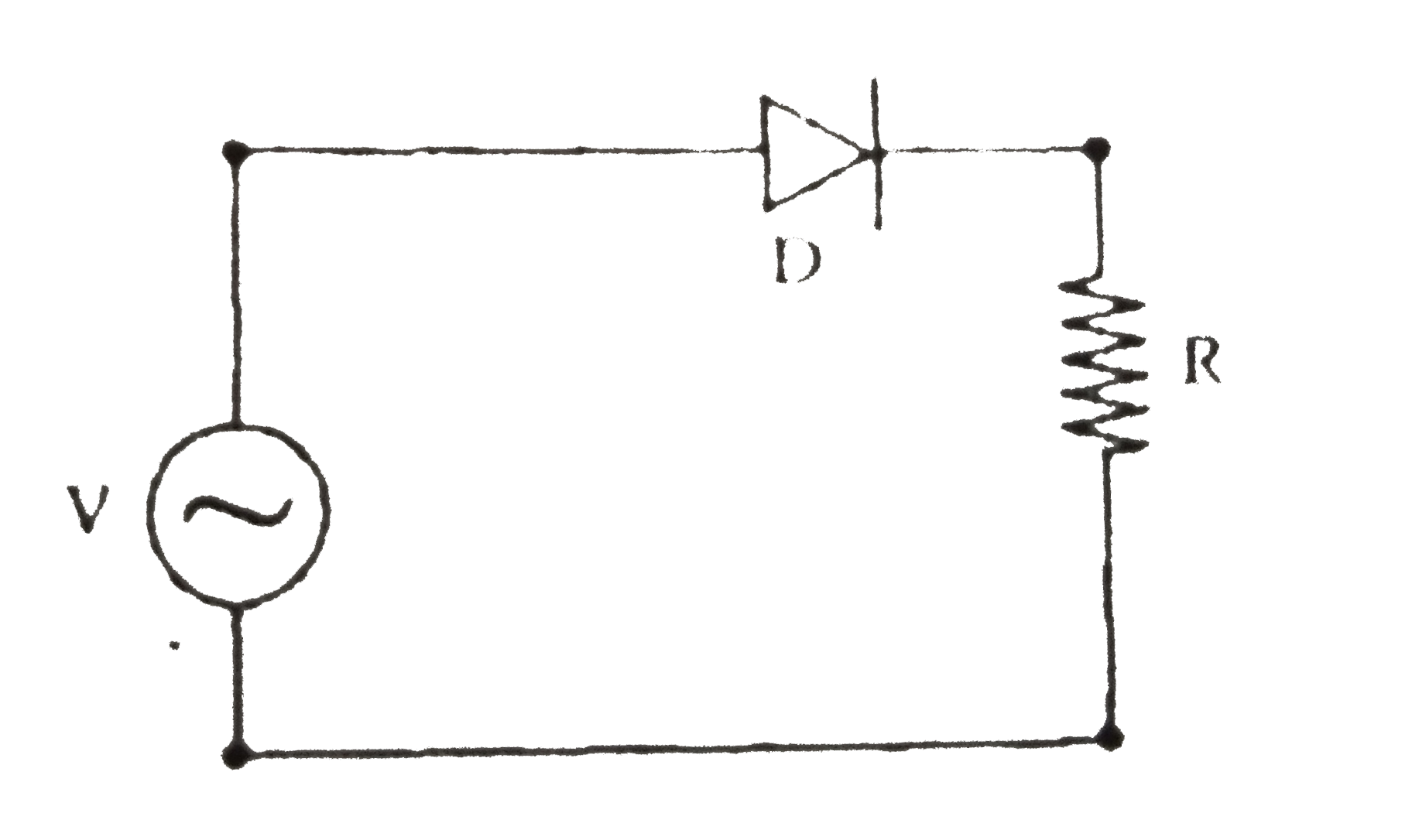
- A p -n junction (D) shown in the figure can act as a rectifier. An alt...
Text Solution
|
- A full-wave p-n diode rectifier uses a load resistor of 1500 Omega . N...
Text Solution
|
- If VA and VB, denote potentials of A and B, then the equivalent resist...
Text Solution
|
- In a silicon diode, the reverse current increases from 10 mu A to 20 ...
Text Solution
|
- In the figure shown, the currents through the series resistance and lo...
Text Solution
|