A
B
C
D
Text Solution
Verified by Experts
The correct Answer is:


Topper's Solved these Questions
SEMICONDUCTOR DEVICES
AAKASH SERIES|Exercise PROBLEMS|41 VideosSEMICONDUCTOR DEVICES
AAKASH SERIES|Exercise EXERCISE - IA|54 VideosSEMICONDUCTOR DEVICES
AAKASH SERIES|Exercise PRACTICE EXERCISE (TRANSISTORS )|8 VideosRAY OPTICS
AAKASH SERIES|Exercise PROBLEMS ( LEVEL-II)|60 VideosUNITS AND MEASUREMENT
AAKASH SERIES|Exercise PRACTICE EXERCISE|45 Videos
Similar Questions
Explore conceptually related problems
AAKASH SERIES-SEMICONDUCTOR DEVICES-PRACTICE EXERCISE (LOGIC GATES )
- The truth table given below is for
Text Solution
|
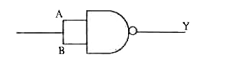
- The logic symbol shown in figure represents
Text Solution
|
- Following diagram performs the logic function of
Text Solution
|
- The name of the gate obtained by the combination as shown is
Text Solution
|
- Which logic gate is represented by the following combination of...
Text Solution
|
- Given below are four logic gate symbols. Those for OR, NOR and NAND ar...
Text Solution
|
- In Boolean expression which gate is expressed as y = bar(A +B)
Text Solution
|
- What will be input of A and B for the Boolean expression bar((A+B)).ba...
Text Solution
|
- Show that AB+bar(AB) is always 1.
Text Solution
|
- The following figure shows a logic gate circuit with two inputs A and ...
Text Solution
|
- The minimum number of gates required to realize this expression...
Text Solution
|
- The combination of NAND gates shown here under are equivalent to
Text Solution
|
- In a given circuit as shown the two input wave forms A and B ...
Text Solution
|
- The combination of the gates shown below produces
Text Solution
|
- The output characteristics of an n-p-n transistor represent ,[IC...
Text Solution
|