Text Solution
Verified by Experts


Topper's Solved these Questions
SEMICONDUCTOR DEVICES
AAKASH SERIES|Exercise EXERCISE - IA|54 VideosSEMICONDUCTOR DEVICES
AAKASH SERIES|Exercise EXERCISE - IB|7 VideosSEMICONDUCTOR DEVICES
AAKASH SERIES|Exercise PRACTICE EXERCISE (LOGIC GATES )|15 VideosRAY OPTICS
AAKASH SERIES|Exercise PROBLEMS ( LEVEL-II)|60 VideosUNITS AND MEASUREMENT
AAKASH SERIES|Exercise PRACTICE EXERCISE|45 Videos
Similar Questions
Explore conceptually related problems
AAKASH SERIES-SEMICONDUCTOR DEVICES-PROBLEMS
- The current through a P-N junction diode is 55mA at a forward bias vol...
Text Solution
|
- If a p-n junction diode, a square input signal of 10V is applied as sh...
Text Solution
|
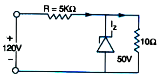
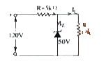
- For the circuit shown in Fig. find 1) the output voltage 2) the vo...
Text Solution
|
- A Zener diode is specified as having a breakdown voltage of 9.1 V,with...
Text Solution
|
- In a single state transistor amplifier, when by 10muA and collector cu...
Text Solution
|
- AP-N-P transistor is used in common-emitter mode in an amplifier circu...
Text Solution
|
- For a transistor beta=45, the change in the voltage across 5kOmega res...
Text Solution
|
- In a transistor beta=45, the change in the voltage across 5 kOmega res...
Text Solution
|
- Current amplification factor of a common base configuration is 0.88. F...
Text Solution
|
- In a transistor, ihe emitter circuit resis- tance is 100Omega and the ...
Text Solution
|
- An n-p-n transistor in a common-emitter mode is used as a simple volta...
Text Solution
|
- In the following common - emitter configuration an n-p-n transistor wi...
Text Solution
|
- The overall gain of a multistage amplifier is 100. When negative feedb...
Text Solution
|
- Calculate the gain of a negative feedback amplifier with an intern...
Text Solution
|
- For a CE-transistor amplifier fig. The audio signal voltage across the...
Text Solution
|
- In a negative feedback amplifier ,the gain without feedback is 100,fee...
Text Solution
|
- A npn transistor in a common emitter mode is used as a simple voltage ...
Text Solution
|
- The Boolean expression of the output Y of the inputs A and B for the c...
Text Solution
|
- The diagram of a logic circuit is given below. The output of the circu...
Text Solution
|
- The logic circuit and its truth table are given, what is the gate X in...
Text Solution
|