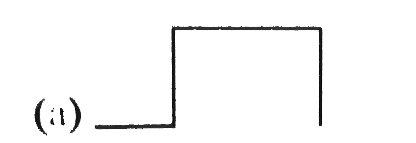
A
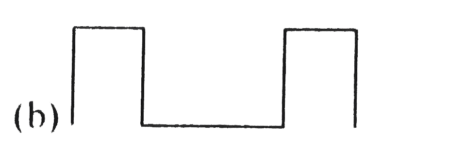
B
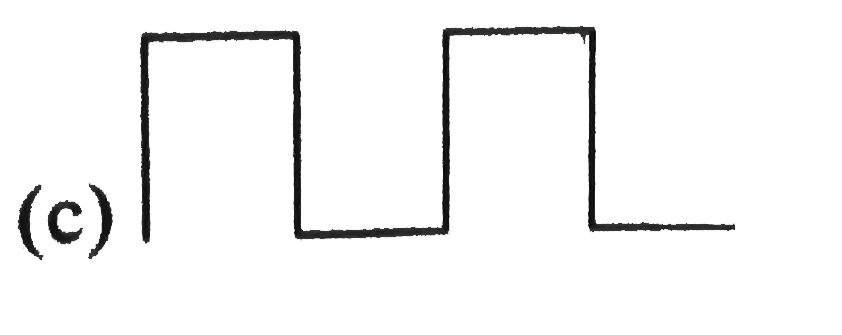
C
D
Text Solution
Verified by Experts
The correct Answer is:


Topper's Solved these Questions
SEMICONDUCTOR ELECTRONICS
A2Z|Exercise Problems Based On Mixed Concepts|32 VideosSEMICONDUCTOR ELECTRONICS
A2Z|Exercise Section B - Assertion Reasoning|22 VideosSEMICONDUCTOR ELECTRONICS
A2Z|Exercise Junction Transistor|47 VideosNUCLEAR PHYSICS
A2Z|Exercise Section D - Chapter End Test|29 VideosSOURCE AND EFFECT OF MAGNETIC FIELD
A2Z|Exercise Section D - Chapter End Test|30 Videos
Similar Questions
Explore conceptually related problems
A2Z-SEMICONDUCTOR ELECTRONICS-Digital Electronics
- The following configuration of gates is equivalent to
Text Solution
|
- In the Boolean algebra bar((bar(A).bar(B))). A equal to
Text Solution
|
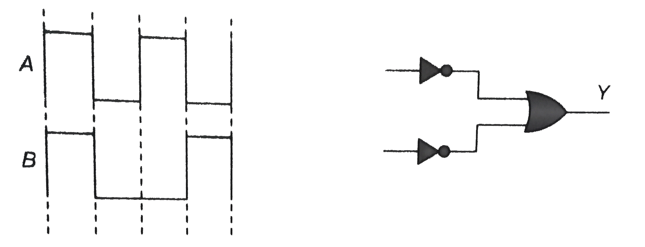
- In the given circuit as shown the two input waveform A and B are appli...
Text Solution
|
- The circuit diagram (see fig.) shows a 'logic combination' with the st...
Text Solution
|
- In order to obtain an output Y=1 form the circuit of fig. the inputs m...
Text Solution
|
- With reference to figure, which of the following is possible?
Text Solution
|
- Name the Gate represented by the following circuit.
Text Solution
|
- The following truth table corresponds to the logic gate |(A,0,0,1,1)...
Text Solution
|
- The combination of 'NAND' gates shown here under (figure) are equivale...
Text Solution
|
- The following truth table corresponds to the logic gate |(A,B,X),(0,...
Text Solution
|
- Which of the following gates corresponds to the truth table given belo...
Text Solution
|
- How many NAND gate are used to from AND gate?
Text Solution
|
- The following truth table belongs to which one of the following four g...
Text Solution
|
- The truth table given below is for: |(A,B,X),(0,0,0),(0,1,0),(1,0,0)...
Text Solution
|
- The truth table given below is for which gate? |(A,B,C),(0,0,1),(0,1...
Text Solution
|
- Given below are four logic tage symboles. Those for OR, NOR and NAND a...
Text Solution
|
- Which of the following gates will have an output of 1?
Text Solution
|
- A truth table is given below. Which of the following has this types fo...
Text Solution
|
- The truth table shown in figure is for |(A,0,0,1,1),(B,0,1,0,1),(Y,1...
Text Solution
|
- For the given combination of gates, if the logic states of inputs A,B,...
Text Solution
|