A
B
C
D
Text Solution
Verified by Experts
The correct Answer is:


Topper's Solved these Questions
SEMICONDUCTOR ELECTRONICS
A2Z|Exercise Problems Based On Mixed Concepts|32 VideosSEMICONDUCTOR ELECTRONICS
A2Z|Exercise Section B - Assertion Reasoning|22 VideosSEMICONDUCTOR ELECTRONICS
A2Z|Exercise Junction Transistor|47 VideosNUCLEAR PHYSICS
A2Z|Exercise Section D - Chapter End Test|29 VideosSOURCE AND EFFECT OF MAGNETIC FIELD
A2Z|Exercise Section D - Chapter End Test|30 Videos
Similar Questions
Explore conceptually related problems
A2Z-SEMICONDUCTOR ELECTRONICS-Digital Electronics
- Given below are four logic tage symboles. Those for OR, NOR and NAND a...
Text Solution
|
- Which of the following gates will have an output of 1?
Text Solution
|
- A truth table is given below. Which of the following has this types fo...
Text Solution
|
- The truth table shown in figure is for |(A,0,0,1,1),(B,0,1,0,1),(Y,1...
Text Solution
|
- For the given combination of gates, if the logic states of inputs A,B,...
Text Solution
|
- The logic behind 'NOR' gate is that it gives
Text Solution
|
- How many NAND gate are used to from AND gate?
Text Solution
|
- Which of the following gates will have an output of 1?
Text Solution
|
- Which of these represents NAND gate?
Text Solution
|
- The given truth table is of |(A,X),(0,1),(1,0)|
Text Solution
|
- What will be the input of A and B for the Boolean expression bar((A+B)...
Text Solution
|
- If A and B are two inputs in AND gate, then AND gate has an output of ...
Text Solution
|
- In order to obtain an output Y=1 form the circuit of fig. the inputs m...
Text Solution
|
- The combination of the gates shown in the figure below produces
Text Solution
|
- Sum of the two binary numbers (1000010)(2) and (110011)(2) is
Text Solution
|
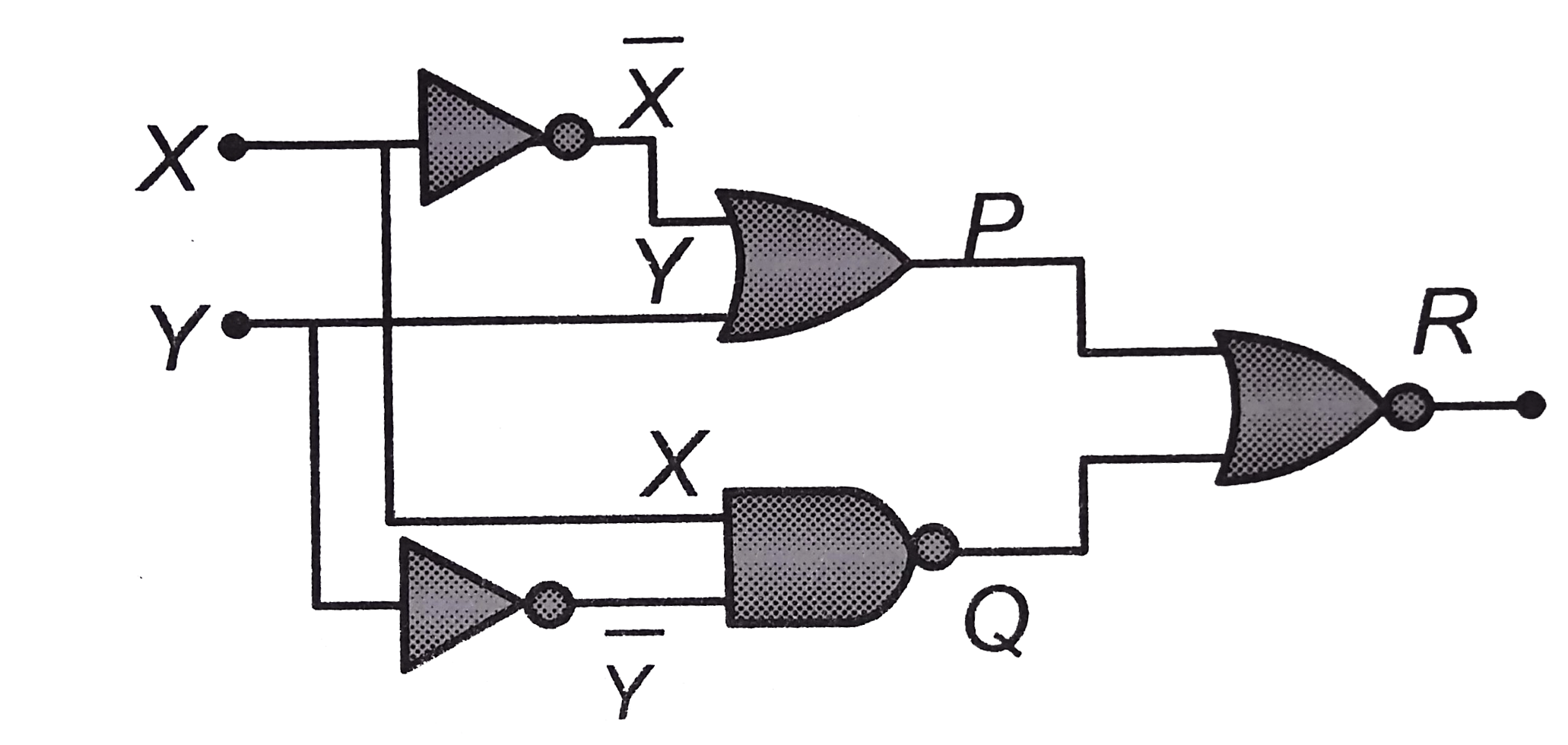
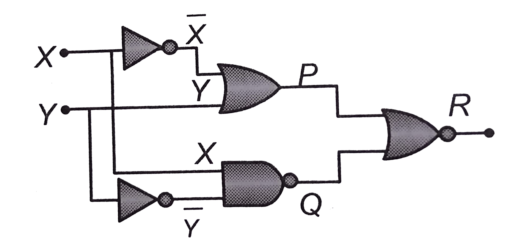
- Figure gives a system of logic gates. From the study of truth table it...
Text Solution
|
- The combination of gates shown below produces
Text Solution
|
- The figure shows two NAND gates followed by a NOR gate. The system is ...
Text Solution
|
- The diagram of a logic circuit is given below. The output F of the cir...
Text Solution
|
- In circuit in the following figure the value of Y is
Text Solution
|