A

B
C
D
Text Solution
Verified by Experts
The correct Answer is:


Topper's Solved these Questions
Similar Questions
Explore conceptually related problems
RESONANCE-SEMICONDUCTORS-Exercise
- The circuit shown in figure (1) Contains two diodes each with a forwar...
Text Solution
|
- The part of a transistor which is most heavily doped to produce large ...
Text Solution
|
- The difference in the variation of resistance with temperature in a me...
Text Solution
|
- When p-n junction diode is forward biased then
Text Solution
|
- The electrical conductivity of a semiconductor increases when electrom...
Text Solution
|
- In a common base ampifier , the phase difference between the input sig...
Text Solution
|
- In a full wave rectifier circuit operating from 50 Hz mains frequency ...
Text Solution
|
- If the ratio of the concentration of electron to that of holes in a se...
Text Solution
|
- In a common base mode of a transition , the collector current is 5.48...
Text Solution
|
- A working transitor with its three legs marked P, Q and R is tested us...
Text Solution
|
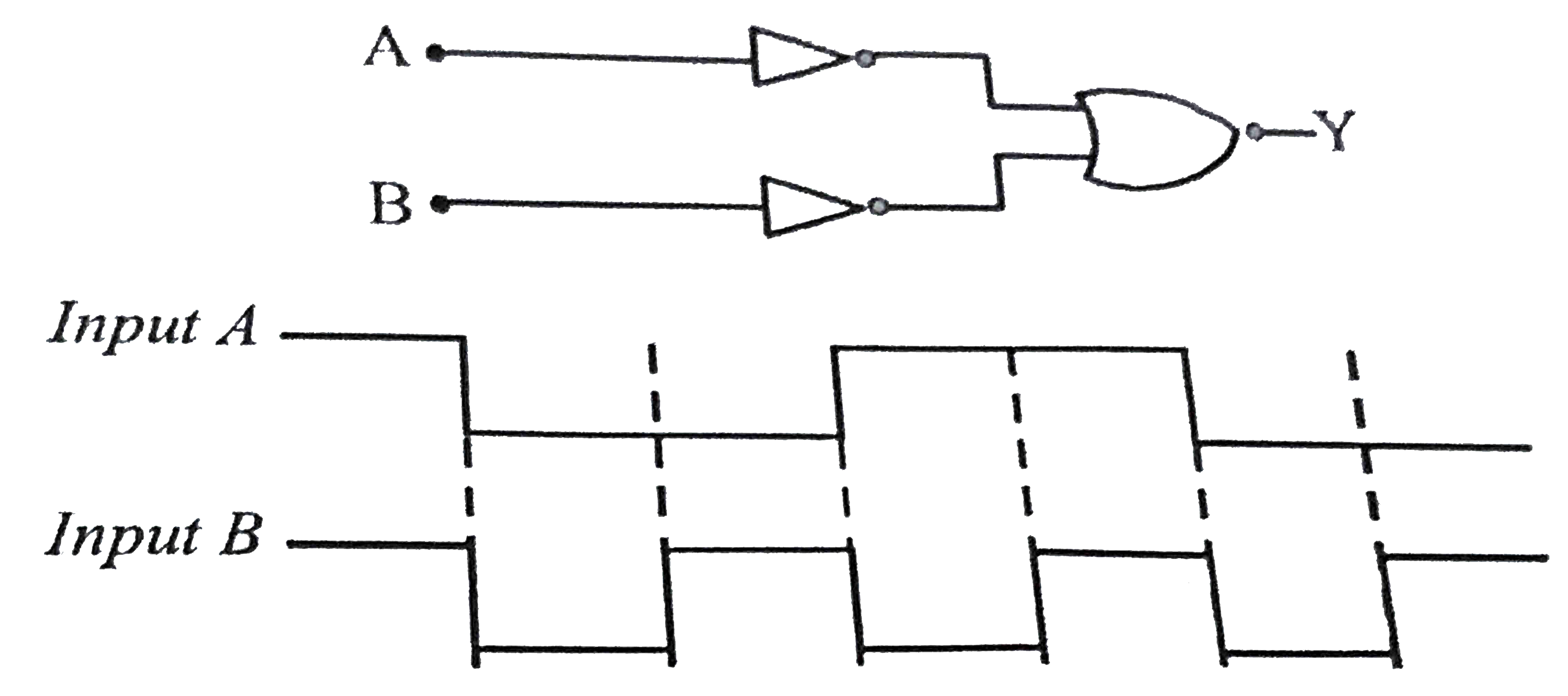
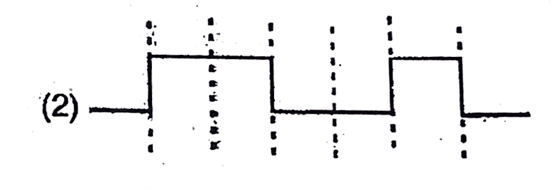
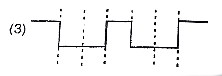
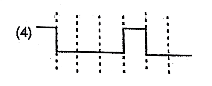
- The logic circuit shown below has the input waveforms ‘A’ and ‘B’ as s...
Text Solution
|
- In a....... baised pn junction , the net flow of holes is from the n ...
Text Solution
|
- In a p-n junction photo cell, the value of the photo electromotive for...
Text Solution
|
- Carbon , silicon and germanium have four valence elcectrons each . The...
Text Solution
|
- For a transistor amplifier, the voltage gain
Text Solution
|
- In a transistor connected in a common emitter mode RC = 4kOmega, R1 = ...
Text Solution
|
- In the figure shown RB = 500K Omega, RC = 8K Omega, VBB= 10.6 V and V(...
Text Solution
|
- Which of the following statement is true for a p-n-p transistor when u...
Text Solution
|
- A resistance R is connected at the n terminal of a p-n junction in ser...
Text Solution
|
- In a transistor, the value of alpha=0.9. Then the value of beta is:
Text Solution
|