


ARIHANT-CAPACITOR-Capacitor
- The space between the conductors of a spherical capacitor is half fill...
Text Solution
|
- Two concentric spherical shells have radii a and b (gt a). Write the ...
Text Solution
|
- Two conducting sphere of radii a and b are placed at separation d. It ...
Text Solution
|
- All capacitors in the network given below are identical with capacitan...
Text Solution
|
- In the given circuit it is known that the capacitor A has a capacitanc...
Text Solution
|
- In the circuit shown in the Figure, find the ratio of potential differ...
Text Solution
|
- In the circuit shown in the figure, find charge on each capacitor.
Text Solution
|
- Two capacitors A and B with capacitors 3 muF and 2 muF are charged to ...
Text Solution
|
- A parallel plate air capacitor has plate area A and separation between...
Text Solution
|
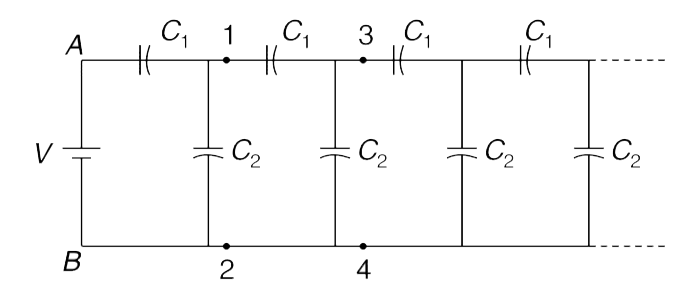
- The circuit shown in the figure continues to infinity. The potential d...
Text Solution
|
- The parallel plate capacitors shown in the Figure have capacitance C(1...
Text Solution
|
- Four large identical metallic plates are placed as shown in the Figure...
Text Solution
|
- In the circuit shown in the figure all the capacitors have capacitance...
Text Solution
|
- There are nine 2 muF capacitors, two 1 muF capacitors and one 4 muF ca...
Text Solution
|
- Two solid conducting spheres of radii R(1) and R(2) are kept at a dist...
Text Solution
|
- Two identical long metal wires having radius a are held parallel to ea...
Text Solution
|
- A particle of mass m and charge + q enters horizontally with speed V(0...
Text Solution
|
- Lower plate of a parallel plate capacitor is fixed on a horizontal ins...
Text Solution
|
- Two identical metal plates with area A and mass m are kept separated b...
Text Solution
|
- One plate of a parallel plate capacitor is tilted by a small angle abo...
Text Solution
|