


ARIHANT-CURRENT ELECTRICITY-Current Electricity
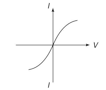
- The current-voltage graph for a resistor is as shown in the figure. Is...
Text Solution
|
- A cylindrical conductor has length l and area of cross section A. Its ...
Text Solution
|
- A conductor has density d and molar mass M. A wire made of this conduc...
Text Solution
|
- A conducting wire of length l and cross sectional area A is used to sh...
Text Solution
|
- A conducting open pipe has shape of a half cylinder of length L. Its s...
Text Solution
|
- It was found that resistance of a cylindrical specimen of a wire does ...
Text Solution
|
- A cylindrical conductor is made so that its resistance is independent ...
Text Solution
|
- A bulb B is connected to a source having constant emf and some interna...
Text Solution
|
- In the circuit shown in the figure R(1) =3 Omega,R(2) = 2 Omega and R(...
Text Solution
|
- Find the equivalent resistance between point a and b in the network sh...
Text Solution
|
- In the circuit shown in the figure, the potential difference between p...
Text Solution
|
- An infinite network of resistances has been made as shown in the figur...
Text Solution
|
- Find equivalent resistance between points A and B in the figure. Each ...
Text Solution
|
- A fuse F(1) is connected across a source of variable voltage and the v...
Text Solution
|
- In the circuit shown in the figure. find I(1) and I(2).
Text Solution
|
- In the network shown calculate current through the cell (I1) and the c...
Text Solution
|
- In the circuit shown, R=2 Omega and V = 20 volt. With switch S open th...
Text Solution
|
- The box shown in the figure has a device which ensures that I(C) = 0.9...
Text Solution
|
- In the circuit shown in figure find the equivalent resistance across p...
Text Solution
|
- Find the percentage change in power supplied by the cell after the swi...
Text Solution
|