Text Solution
Verified by Experts
The correct Answer is:


Topper's Solved these Questions
Similar Questions
Explore conceptually related problems
ARIHANT-ELECTROMAGNETIC INDUCTION-Level 3
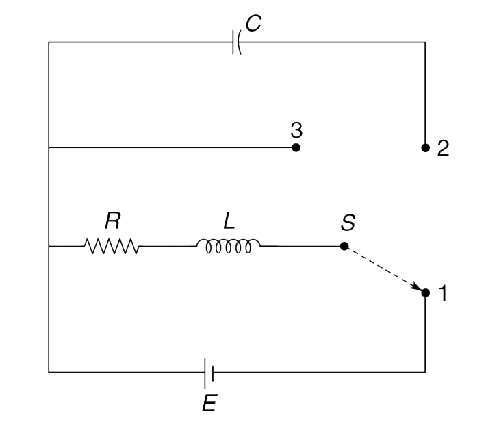
- In the circuit arrangement shown in Figure, the three way switch S is ...
Text Solution
|
- A short bar magnet having magnetic dipole moment M is moving along the...
Text Solution
|
- A region of width L contains a uniform magnetic field B directed into ...
Text Solution
|
- A metallic pulley is in the shape of a disc of radius a. It can rotate...
Text Solution
|
- Figure shows a square conducting frame and a long wire-both lying in t...
Text Solution
|
- A square loop of side length d has a capacitor of capacitance C and th...
Text Solution
|
- There exists a uniform magnetic field perpendicular to the plane of th...
Text Solution
|
- The Figure shows an electromagnetic gun. A bar of mass m, resistance R...
Text Solution
|
- A thin solenoid is made of a large number of turns of very thin wire t...
Text Solution
|
- A uniform magnetic field B exists perpendicular to the plane of the Fi...
Text Solution
|
- Two conducting sphere of radius R are placed at a large distance from ...
Text Solution
|
- In the circuit shown in the figure, switch S is closed at time t = 0. ...
Text Solution
|
- In the circuit shown, switch S is kept closed and the circuit is in st...
Text Solution
|