Home
Class 12
PHYSICS
The circuit shown in the figure is used ...

The circuit shown in the figure is used to transfer energy from one capacitor to another. Initially capacitor of capacitance `C_(1) = C_(0)` is charged to a potential difference of `V_(0)`. Switch `S_(1)` is closed at time t = 0. After some time `S_(1)` is opened and `S_(2)` is closed simultaneously. At time `t = T, S_(2)` was opened and it was found that the potential difference across capacitor of capacitance `C_(2) = (C_(0))/(9)` was `3V_(0)`. Find the smallest possible value of time T. The coil has inductance L. Assume no resistance.

Text Solution

Verified by Experts

The correct Answer is:
`T_(min) = (2pi)/(3) sqrt(LC_(0))`
Promotional Banner

Topper's Solved these Questions

  • ELECTROMAGNETIC INDUCTION

    ARIHANT|Exercise Level 3|12 Videos
  • ELECTROMAGNETIC INDUCTION

    ARIHANT|Exercise Level 3|12 Videos
  • CURRENT ELECTRICITY

    ARIHANT|Exercise Current Electricity|105 Videos
  • ELECTROSTATICS

    ARIHANT|Exercise Level 3|59 Videos

Similar Questions

Explore conceptually related problems

In the circuit shown in figure-3.345 the capacitor of capacitance C is charged to a potential difference V. The current in the circuit just after the closing of switch S is :

The switch S in the circuit diagram is closed at t = 0. The charge on capacitors at any time is

In the circuit shown in fig. C_1 = 2C_2 Initially, capacitor C_1 is charged to a potential of V. The current in the circuit just after the switch S is closed is

In the circuit shown, the capacitor C_1 is initially charged with charge q_0 . The switch S is closed at time t = 0 . The charge on C_2 after time t is

A capacitor of capacitance C_(1) is charged to a potential difference V and then connected with an uncharged capacitor of capacitance C_(2) a resistance R. The switch is closed at t = 0. Choose the correct option(s):

Two capacitors of capacitance C and 3C are charged to potential difference V_(0) and 2V_(0) respectively, and connected to an inductor of inductance L as shown in figure. Initially the current in the inductor is zero. Now, the switch S is closed. Potential difference across capacitor of capacitance 3C when the current in the cirucit is maximum is :

Two capacitors of capacitance C and 3C are charged to potential difference V_(0) and 2V_(0) respectively, and connected to an inductor of inductance L as shown in figure. Initially the current in the inductor is zero. Now, the switch S is closed. Potential difference across capacitor of capacitance C when the current in the cirucit is maximum is

In the circuit shown in the figure, if switches S_(1) and S_(2) have been closed for a long time, then charge on the capacitor.

ARIHANT-ELECTROMAGNETIC INDUCTION-Level 2
  1. A cylindrical region of radius R is filled with a uniform magnetic fie...

    Text Solution

    |

  2. cylindrical volume of radius R has a uniform axial magnetic field B, w...

    Text Solution

    |

  3. A uniform magnetic field B exists in a circular region of radius R. th...

    Text Solution

    |

  4. A thin beam of n identical positively charged particle are constrained...

    Text Solution

    |

  5. There is a long cylinder of radius R having a cylindrical cavity of ra...

    Text Solution

    |

  6. A uniform magnetic field B exists in a region of circular cross sectio...

    Text Solution

    |

  7. A conducting ring of mass m = pi kg and radius R = (1)/(2)m is kept on...

    Text Solution

    |

  8. A tightly wound solenoid of length l and cross sectional area A(1) is ...

    Text Solution

    |

  9. In the last problem calculate the emf induced in the outer coil if the...

    Text Solution

    |

  10. In the last problem, calculate the force needed to pull out the inner ...

    Text Solution

    |

  11. Two ends of an inductor of inductance L is connected to two parallel c...

    Text Solution

    |

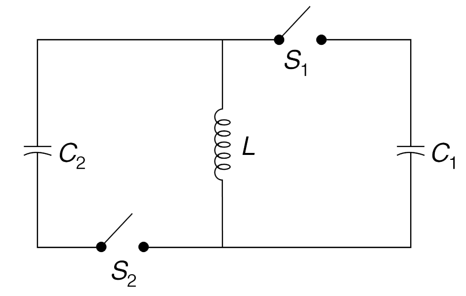
  12. In the circuit shown in Figure, switch S(1) is kept closed and S(2) op...

    Text Solution

    |

  13. A ring is made of a nearly superconducting mate- rial. Inductance of t...

    Text Solution

    |

  14. In the circuit shown, the switch ‘S’ has been closed for a long time a...

    Text Solution

    |

  15. In the circuit shown, switch S(2) is open and S(1) is closed since lon...

    Text Solution

    |

  16. The circuit shown in the figure is used to transfer energy from one ca...

    Text Solution

    |

  17. A pure inductor coil having inductance L is connected to a resistance ...

    Text Solution

    |

  18. The circuit shown in figure has two identical capacitors one of which ...

    Text Solution

    |

  19. The capacitors shown in the circuit have capacitance C(1) = C and C(2)...

    Text Solution

    |

  20. In the circuit shown in figure S(1) is open and, S(2) and S(3) are clo...

    Text Solution

    |