Text Solution
Verified by Experts
The correct Answer is:


Topper's Solved these Questions
Similar Questions
Explore conceptually related problems
ARIHANT-CURRENT ELECTRICITY-Current Electricity
- Find equivalent resistance between points A and B in the figure. Each ...
Text Solution
|
- A fuse F(1) is connected across a source of variable voltage and the v...
Text Solution
|
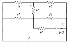
- In the circuit shown in the figure. find I(1) and I(2).
Text Solution
|
- In the network shown calculate current through the cell (I1) and the c...
Text Solution
|
- In the circuit shown, R=2 Omega and V = 20 volt. With switch S open th...
Text Solution
|
- The box shown in the figure has a device which ensures that I(C) = 0.9...
Text Solution
|
- In the circuit shown in figure find the equivalent resistance across p...
Text Solution
|
- Find the percentage change in power supplied by the cell after the swi...
Text Solution
|
- A and B are two identical bulbs of 40 W connected to a V = 12 volt cel...
Text Solution
|
- Find equivalent resistance between points A and B in the circuit shown...
Text Solution
|
- Find current through the cell and potential difference between A and D...
Text Solution
|
- Eight identical 1 volt cells are connected to make a ring as shown in ...
Text Solution
|
- A battery of 120 V and internal resistance r = 0.5 Omega is used to ch...
Text Solution
|
- A voltmeter of resistance R(V) and an ammeter of resistance R(A) are c...
Text Solution
|
- In the circuit shown in the figure, cell is ideal and R(2) = 100 Omega...
Text Solution
|
- In the circuit shown, an ideal cell of emf E is connected in series to...
Text Solution
|
- In the circuit shown, which way would you move the sliding contact, to...
Text Solution
|
- In the circuit shown in figure. AB is a uniform wire of length L and r...
Text Solution
|
- A rotary potentiometer has a circular resistance (C) and a conducting ...
Text Solution
|
- In the figure shown PQ is a potentiometer wire. When galvanometer is c...
Text Solution
|