Text Solution
Verified by Experts
The correct Answer is:


Topper's Solved these Questions
Similar Questions
Explore conceptually related problems
ARIHANT-CURRENT ELECTRICITY-Current Electricity
- In the circuit shown in figure B(1), B(2) and B(3) are identical bulbs...
Text Solution
|
- When the applied potential difference across a circuit element is incr...
Text Solution
|
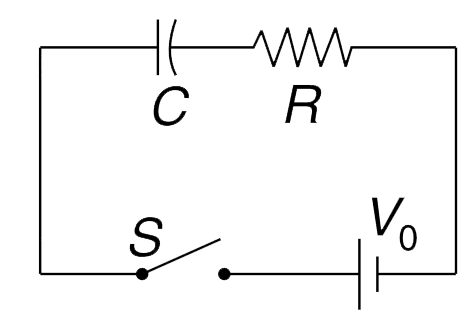
- In the circuit shown the switch is closed at time t = 0. Plot the foll...
Text Solution
|
- A capacitor having initial change q(0) and capacitance C is connected ...
Text Solution
|
- A parallel plate capacitor has plate area A and separation between the...
Text Solution
|
- Consider the circuit shown in the figure. The switch has been in posit...
Text Solution
|
- An electric bulb has a solid cylindrical filament of length l and radi...
Text Solution
|
- A battery of emf V and internal resistance r is connected to N identic...
Text Solution
|
- A copper wire of length 5 cm carries a current of density j = 1 A (mm)...
Text Solution
|
- A conducting plate of thickness t is in the shape of an arc. Its inner...
Text Solution
|
- A conductor having resistivity rho is bent in the shape of a half cyli...
Text Solution
|
- A metallic wire has variable cross sectional area. Cross sectional are...
Text Solution
|
- A tungsten filament bulb is connected to a variable voltage supply. Th...
Text Solution
|
- The figure shows the tungsten filament with constant diameter except a...
Text Solution
|
- Two cylindrical rods, of different material, are joined as shown. The ...
Text Solution
|
- The current (I) – voltage (V) characteristic of three devices A, B and...
Text Solution
|
- The current – voltage characteristic of an electric device is as shown...
Text Solution
|
- ABCD is a uniform circular wire of resistance 16 Omega and AOC and BD ...
Text Solution
|
- In the circuit shown in the fig the equivalent resistance between a an...
Text Solution
|
- (a) In the circuit shown in figure, all resistances are identical when...
Text Solution
|