Home
Class 12
PHYSICS
In the circuit shown in the figure, two ...

In the circuit shown in the figure, two resistors `R_(1) and R_(2)` have been connected in series to an ideal cell. When a voltmeter is connected across `R_(1)` its reading is `V_(1) = 4.0` volt and when the same voltmeter is connected across `R_(2)` its reading is `V_(2) = 6.0` volt. The reading of the voltmeter when it is connected across the cell is `V_(3) = 12.0` volt. Find the actual across `R_(1)` in the circuit.

Text Solution

Verified by Experts

The correct Answer is:
4.8 V
Promotional Banner

Topper's Solved these Questions

  • CAPACITOR

    ARIHANT|Exercise Capacitor|50 Videos
  • ELECTROMAGNETIC INDUCTION

    ARIHANT|Exercise Level 3|12 Videos

Similar Questions

Explore conceptually related problems

For three circuits, shown here the same two resistors R_(1) and R_(2) have been connected in parallel in all the circuits but the voltmeter and the ammeter have been connected in three different positions. The relation between the three voltmeter and ammeter readings would be :

In Fig. 6.59 , when an ideal voltmetre is connected across 4000 Omega resistance, it reads 30 V . If the voltmeter is connected across 3000 Omega resistance, it will read

In the circuit, a voltmeter reads 30 V when it is connected across 400 Omega resistance. Calculate what the same voltmeter will read when it is connected across the 300Omega resistance?

Shown two ideal voltmeters and an ammeter, which are connected across the various circuit elements. If the voltmeter connected across 9Omega resistance reads 4.5 V, then answer the following problems. The reading of the voltmeter connected across 20Omega resistance is

In the circuit given below, a voltmeter reads 20V when it is connected across 400Omega resistance. Calculate what the same voltmeter will read when connected across the 200Omega resistance.

Shown two ideal voltmeters and an ammeter, which are connected across the various circuit elements. If the voltmeter connected across 9Omega resistance reads 4.5 V, then answer the following problems. The reading of the ammeter is

When an ideal voltmeter is connected between the [points E and F the reading of the meter is V_(0) . When an ideal ammeter is connected between E and F, reading is I_(0) find the current I through resistor R connected between E and F.

In the circuit shown in figure-3 .3 89, the voltmeter reads 30V when it is connected across 400 Omega resistance. Calculate what the same voltmeter will read when it is connected across the 300 Omega resistance.

ARIHANT-CURRENT ELECTRICITY-Current Electricity
  1. In the circuit shown in figure a current I = 600 muA enters through A ...

    Text Solution

    |

  2. In the circuit shown, each resistor has a resistance R(X) which depend...

    Text Solution

    |

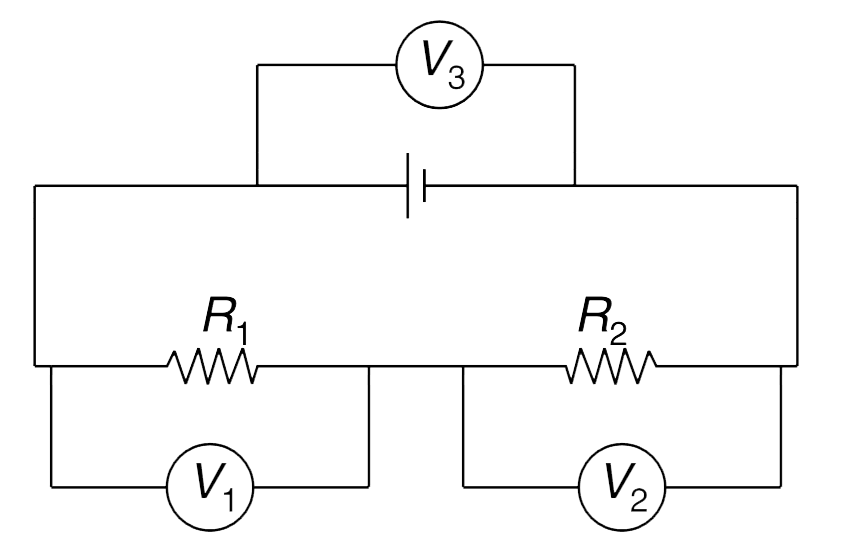
  3. In the circuit shown in the figure, two resistors R(1) and R(2) have b...

    Text Solution

    |

  4. An ohm-meter is a device that measures an unknown resistance. A simple...

    Text Solution

    |

  5. To enhance the sensitivity, an Ammeter is to be designed with two kind...

    Text Solution

    |

  6. Three ammeters — 1, 2 and 3 have different internal resistances r(1), ...

    Text Solution

    |

  7. Three identical capacitors, each of capacitance C are connected in ser...

    Text Solution

    |

  8. Assume that clouds are distributed around the entire earth at a height...

    Text Solution

    |

  9. The capacitor A shown in fig. has a capacitance C(1) = 3 mu F. The die...

    Text Solution

    |

  10. In the circuit shown in fig. the switch is kept closed in position 1 f...

    Text Solution

    |

  11. Find the charge on the capacitor in the circuit shown in fig.

    Text Solution

    |

  12. A parallel plate capacitor has its two plates connected to an ideal sp...

    Text Solution

    |

  13. In the last problem calculate the amount of heat dissipated in the res...

    Text Solution

    |

  14. In the circuit shown in the figure R(1) = R(2) = 5 Omega, C(1) = C(2) ...

    Text Solution

    |

  15. A charged capacitor (C(1) = 3 mu F) is getting discharged in the circu...

    Text Solution

    |

  16. In the Fig. two neutral spherical conductors of radii 2a and a are sep...

    Text Solution

    |

  17. Consider two circuits given below. When switches S(1) and S(2) are clo...

    Text Solution

    |

  18. In the circuit shown in fig. the capacitor is initially uncharged. Two...

    Text Solution

    |

  19. An infinite ladder network consisting of all equal resistances, r = (1...

    Text Solution

    |

  20. In the circuit shown in the figure, switch S is closed at time t = 0. ...

    Text Solution

    |