Text Solution
Verified by Experts


Topper's Solved these Questions
UNIT–III & UNIT–IV MAGNETIC EFFECTS OF CURRENT AND MAGNETISM & E.M.I. AND ALTERNATING CURRENT
CBSE COMPLEMENTARY MATERIAL|Exercise SHORT ANSWER QUESTIONS (2 Marks)|41 VideosUNIT–III & UNIT–IV MAGNETIC EFFECTS OF CURRENT AND MAGNETISM & E.M.I. AND ALTERNATING CURRENT
CBSE COMPLEMENTARY MATERIAL|Exercise SHORT ANSWERS QUESTIONS (3 Marks)|27 VideosSAMPLE QUESTION PAPER 2019
CBSE COMPLEMENTARY MATERIAL|Exercise Section C|19 Videos
Similar Questions
Explore conceptually related problems
CBSE COMPLEMENTARY MATERIAL-UNIT–III & UNIT–IV MAGNETIC EFFECTS OF CURRENT AND MAGNETISM & E.M.I. AND ALTERNATING CURRENT-(NUMERICALS)
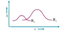
- Current versus voltage (I – v) graphs for two different series L–C–R c...
Text Solution
|
- An electron travels on a circular path of radius 10 m in a magnetic fi...
Text Solution
|
- A charge particle of mass m and charge q entered into magnetic field B...
Text Solution
|
- Calculate the magnetic field due to a circular coil of 500 turns and o...
Text Solution
|
- An electron of kinetic energy 10 keV moves perpendicular to the direct...
Text Solution
|
- If the current sensitivity of a moving coil galvanometer is increased ...
Text Solution
|
- A uniform wire is bent into one turn circular loop and same wire is ag...
Text Solution
|
- A horizontal electrical power line carries a current of 90A from east ...
Text Solution
|
- A galvanometer with a coil of resistance 90Omega shows full scale defl...
Text Solution
|
- Two identical circular loops P and Q carrying equal currents are place...
Text Solution
|
- A cyclotron’s oscillator frequency is 10 MHz. What should be the opera...
Text Solution
|
- The coil of a galvanometer is 0.02 × 0.08 m2. It consists of 200 turns...
Text Solution
|
- A voltmeter reads 5V at full scale deflection and is graded according ...
Text Solution
|
- A short bar magnet placed with its axis at 30° with an external field ...
Text Solution
|
- What is the magnitude of the equatorial and axial fields due to a bar ...
Text Solution
|
- What is the magnitude of magnetic force per unit length on a wire carr...
Text Solution
|
- Two moving coil metres M(1) and M(2) have the following particular R(1...
Text Solution
|
- Figure shows a small magnetised needle P placed at a point O. The arro...
Text Solution
|
- Figure shows a small magnetised needle P placed at a point O. The arro...
Text Solution
|
- Figure shows a small magnetised needle P placed at a point O. The arro...
Text Solution
|
- In the circuit, the current is to be measured. What is the value of th...
Text Solution
|