Text Solution
Verified by Experts


Topper's Solved these Questions
UNIT–III & UNIT–IV MAGNETIC EFFECTS OF CURRENT AND MAGNETISM & E.M.I. AND ALTERNATING CURRENT
CBSE COMPLEMENTARY MATERIAL|Exercise SHORT ANSWERS QUESTIONS (3 Marks)|27 VideosUNIT–III & UNIT–IV MAGNETIC EFFECTS OF CURRENT AND MAGNETISM & E.M.I. AND ALTERNATING CURRENT
CBSE COMPLEMENTARY MATERIAL|Exercise LONG ANSWER QUESTIONS (5 Marks)|5 VideosUNIT–III & UNIT–IV MAGNETIC EFFECTS OF CURRENT AND MAGNETISM & E.M.I. AND ALTERNATING CURRENT
CBSE COMPLEMENTARY MATERIAL|Exercise (NUMERICALS)|57 VideosSAMPLE QUESTION PAPER 2019
CBSE COMPLEMENTARY MATERIAL|Exercise Section C|19 Videos
Similar Questions
Explore conceptually related problems
CBSE COMPLEMENTARY MATERIAL-UNIT–III & UNIT–IV MAGNETIC EFFECTS OF CURRENT AND MAGNETISM & E.M.I. AND ALTERNATING CURRENT-SHORT ANSWER QUESTIONS (2 Marks)
- An ac source of rms voltage V is put across a series combination of an...
Text Solution
|
- A bar magnet is falling with some acceleration ‘a’ along the vertical ...
Text Solution
|
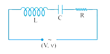
- The series L–C–R circuit shown in fig. is in resonance state. What is ...
Text Solution
|
- The division marked on the scale of an a.c. ammeter are not equally sp...
Text Solution
|
- Circuit shown here uses an air filled parallel plate capacitor. A mica...
Text Solution
|
- In the figure shown, coils P and Q are identical and moving apart with...
Text Solution
|
- An electron is passing through a field but no force is acting on it. U...
Text Solution
|
- A 1.5 muF capacitor is charged to 57V. The charging battery is then di...
Text Solution
|
- The self inductance of the motor of an electric fan is 10H. In order t...
Text Solution
|
- A galvanometer needs 50mV for full scale deflection of 50 Divisions. F...
Text Solution
|
- A light bulb and an open coil inductor are connected to an ac source t...
Text Solution
|
- Show that in the free oscillations of an LC circuit, the sum of energi...
Text Solution
|
- Show that the potential difference across the LC combination is zero a...
Text Solution
|
- When a large amount of current is passing through solenoid, it contrac...
Text Solution
|
- Answer the following questions : (a) In any a.c. circuit, is the app...
Text Solution
|
- A bar magnet M is dropped so that is falls vertically through the coil...
Text Solution
|
- How does the mutual inductance of a pair of coils change when (i) di...
Text Solution
|
- Two circular conductors are perpendicular to each other as shown in fi...
Text Solution
|
- What is a radial magnetic field? Why is it required in a galvanometer ...
Text Solution
|
- The hysterisis loop of material depends not only on the nature of mate...
Text Solution
|