Home
Class 12
PHYSICS
In a series C-R circuit shown in figureu...

In a series `C-R` circuit shown in figureure, the applied voltage is `10 V` and the voltage across capacitor is found to`8 V`. The voltage across `R`, and the phase difference between current and the applied voltage will respectively be
.

A

6V, `tan^(-1)(4/3)`

B

`3V, tan^(-1)(3/4)`

C

`6V, tan^(-1)(5/3)`

D

None of these

Text Solution

Verified by Experts

The correct Answer is:
A

We know that, for series R-C circuit
`V^(2)=V_(C)^(2)+V_(R)^(2)`

`100 = 64 + V_(R)^(2) =36 rArr V_(R) = sqrt(36) = 6V`
Also, `tanphi = V_(C)/V_(R) rArr tanphi = 8/6`
`tanphi = 4/3`
`therefore phi=tan^(-1)(4/3)`
Promotional Banner

Topper's Solved these Questions

  • SOLVED PAPERS 2018

    DC PANDEY ENGLISH|Exercise Assertion and Reasons|10 Videos
  • SOLVED PAPERS 2018

    DC PANDEY ENGLISH|Exercise JIPMER|22 Videos
  • SOLVED PAPERS 2018

    DC PANDEY ENGLISH|Exercise JIPMER|22 Videos
  • SOLVED PAPER 2017

    DC PANDEY ENGLISH|Exercise Solved papers 2017(JIPMER)|32 Videos
  • WAVE OPTICS

    DC PANDEY ENGLISH|Exercise For JEE Advanced E. Integer Type Questions|13 Videos

Similar Questions

Explore conceptually related problems

In the circuit shown in the figure, the total charge is 750 mu C and the voltage across capacitor C_2 is 20 V. Then the charge on capacitor C_2 is:

The phase difference between voltage and current in series L-C circuit is

In series LCR circuit, the phase difference between voltage across L and voltage across C is

In a series L-C circuit, the applied voltage is V_0. if omega is very low, then the voltage drop across the inductor V_L and capacitor V_C are .

In a series L-C-R circuit, currenrt in the circuit is 11A when the applied voltage is 220 V . voltage across the caspcitor is 200 V . If the value of resistor is 20 Omega , then the voltage across the unknown inductor is

An Ac voltage V=V_0 sin 100t is applied to the circuit, the phase difference between current and voltage is found to be pi/4 , then .

An Ac voltage V=V_0 sin 100t is applied to the circuit, the phase difference between current and voltage is found to be pi/4 , then .

In the LCR circuit shown in figure unknown resistance and alternating voltage source are connected.When swith S is closed then there is a phase difference of pi/4 between current and applied voltage and voltage across resister is 100/sqrt2 V .When switch is open current and applied voltage are in same phase.Neglecting resistance of connecting wire answer the following questions : Peak voltage of applied voltage sources is:

In a series LCR circuit resistance R = 10Omega and the impedance Z = 10 Omega The phase difference between the current and the voltage is

In the LCR circuit shown in figure unknown resistance and alternating voltage source are connected.When swith S is closed then there is a phase difference of pi/4 between current and applied voltage and voltage across resister is 100/sqrt2 V .When switch is open current and applied voltage are in same phase.Neglecting resistance of connecting wire answer the following questions : Resonance frequency of circuit is:

DC PANDEY ENGLISH-SOLVED PAPERS 2018-AIIMS
  1. Positive charge Q is distributed uniformly over a circular ring of rad...

    Text Solution

    |

  2. An infinite number of identical capacitors each of capacitance 1 mF ar...

    Text Solution

    |

  3. In the circuit in fig. If no current flows through the galvanometer wh...

    Text Solution

    |

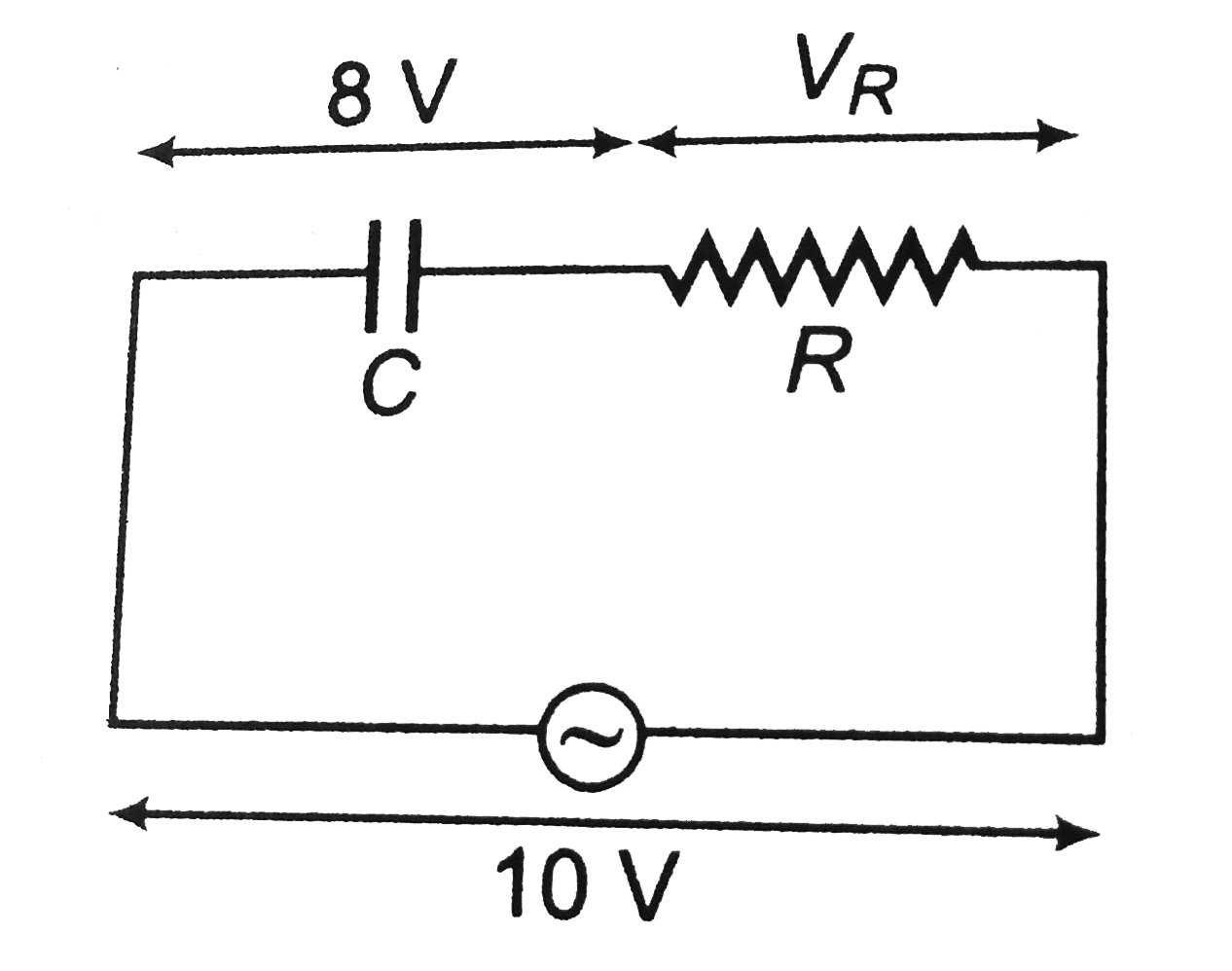
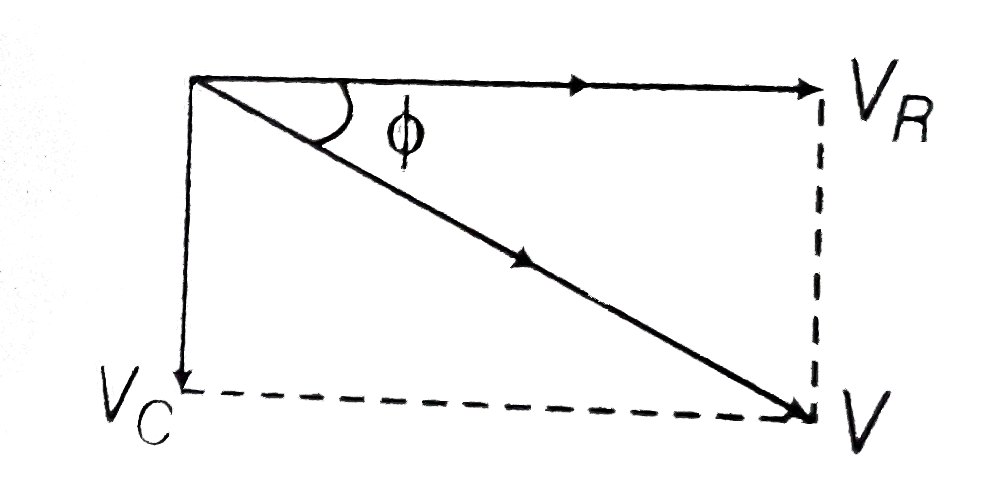
  4. In a series C-R circuit shown in figureure, the applied voltage is 10 ...

    Text Solution

    |

  5. A system S consists of two coils A and B. The coil, A carries a steady...

    Text Solution

    |

  6. A long straight wire, carrying current I, is bent at its midpoint to f...

    Text Solution

    |

  7. An element dvecl=dxhati (where dx=1cm) is placed at the origin and car...

    Text Solution

    |

  8. The coil in figure carries current i=2.00 A in the direction indicated...

    Text Solution

    |

  9. Consider the following figure, a uniform magnetic field of 0.2 T is di...

    Text Solution

    |

  10. An idal coil of 10 is connected in series with a resitance of 5Omega a...

    Text Solution

    |

  11. In the circuit, shown the galvanometer G of resistance 60Omega is shif...

    Text Solution

    |

  12. In a circuit L, C and R are connected in series with an alternating vo...

    Text Solution

    |

  13. The log - log graph between the energy E of an electron and its de - B...

    Text Solution

    |

  14. The half life of a radioactive substance is 20 minutes . The approxima...

    Text Solution

    |

  15. The diode used at a constant potential drop of 0.5 V at all currents a...

    Text Solution

    |

  16. An upolarised beam of intensity 2a^(2) passes through a thin polarioid...

    Text Solution

    |

  17. A hydrogen like atom of atomic number Z is in and excited state of qua...

    Text Solution

    |

  18. A diode detector is used to detect an amplitude modulated wave of 60% ...

    Text Solution

    |

  19. A circular loop of radius 0.3 cm lies parallel to amuch bigger circula...

    Text Solution

    |

  20. In the adjoining circuit diagram, the readings of ammeter and voltmete...

    Text Solution

    |