A
B
C
D
Text Solution
Verified by Experts
The correct Answer is:


Topper's Solved these Questions
Similar Questions
Explore conceptually related problems
VMC MODULES ENGLISH-JEE MAIN REVISION TEST - 18-PHYSICS - SECTION 2
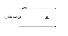
- The output of the given circuit in figure:
Text Solution
|
- The velocity time graph of a particle executing SHM is shown. The maxi...
Text Solution
|
- Length AB in figure is 5 m. The body is released from point C. Frictio...
Text Solution
|
- A parallel plate capacitor having plates of area S and plate separatio...
Text Solution
|
- Half - lives of two radioactive elements A and B are 20 minutes and 40...
Text Solution
|
- A single slit of width 0.1 mm is illuminated by a parallel beam of lig...
Text Solution
|