


Topper's Solved these Questions
SAMPLE PAPER 2023 TERM I
CBSE MODEL PAPER|Exercise SECTION C |7 VideosSAMPLE PAPER 2023 TERM I
CBSE MODEL PAPER|Exercise SECTION D |4 VideosSAMPLE PAPER 2023 TERM I
CBSE MODEL PAPER|Exercise SECTION D |4 VideosSAMPLE PAPER 2022 TERM II
CBSE MODEL PAPER|Exercise SECTION B|16 VideosSAMPLE QUESTION PAPER (THEORY)
CBSE MODEL PAPER|Exercise Section – E|6 Videos
Similar Questions
Explore conceptually related problems
CBSE MODEL PAPER-SAMPLE PAPER 2023 TERM I-SECTION B
- Electromagnetic waves with wavelength (i) lambda(1) is used in satel...
Text Solution
|
- A uniform magnetic field gets modified as shown in figure. When two sp...
Text Solution
|
- What is the nuclear radius of Fe^(125), if that of Al^(27) is 3.6 ferm...
Text Solution
|
- The short weve length limit for the Lyman series of the hydrogen spect...
Text Solution
|
- A biconcave lens made of a transparent material of refractive index 1...
Text Solution
|
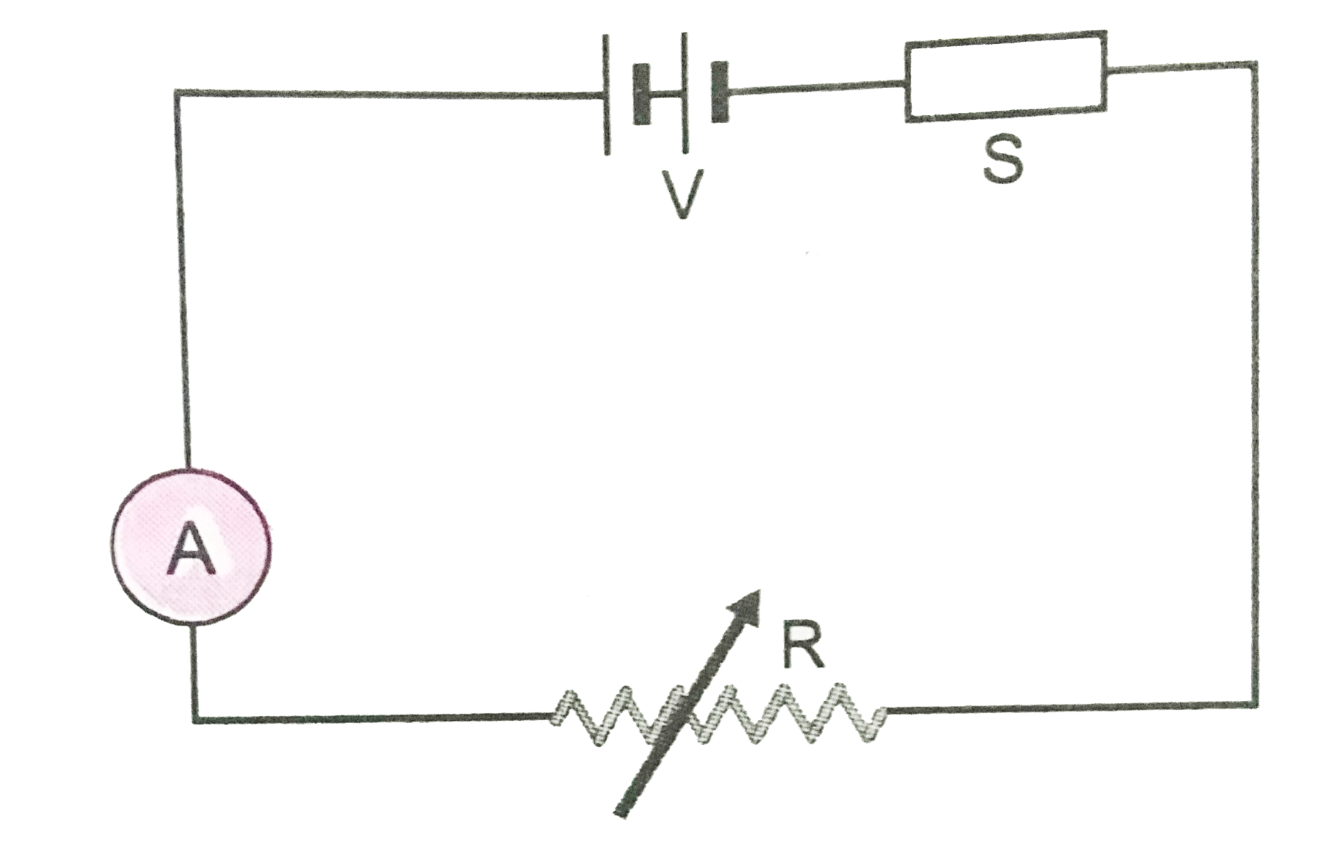
- The diagram Fig.12 shown a piece of pure semiconductor S in series wit...
Text Solution
|
- The graph of potential barrier versus width of depletion region for an...
Text Solution
|
- A narrow slit is illuminated by a parallel beam of monochromatic light...
Text Solution
|
- Two large, thin metal plates are parallel and close to each other. On ...
Text Solution
|