Home
Class 12
PHYSICS
In the circuit shown in figure E,F, G an...

In the circuit shown in figure E,F, G and H are cell of emf 2,1,3, and `1 V` respectively. The resistances 2,1,3 and 1(Omega)are their respective internal resistance .Calculate (a)the potential difference between B and D and (b) the potential differences across the terminals of each of each of the cells G and H.

A

`(21)/(12)V.`

B

`(2)/(13)V.`

C

`(21)/(14)V.`

D

`(21)/(13)V.`

Text Solution

Verified by Experts

The correct Answer is:
D

Suppose a current i_(1) goes in the branch BAD and current i_(2) in the branch DCB. The current in DB will be i_(1)-i_(2) from the junction law. The circuit with the currents shown is redrawn in figure. Applying the loop law to BADB we ge,
`(2(Omega))i_(1)-2V+1V+(1(Omega))i_(1)+(2(Omega))(i_(1)-i_(2))=0`
`(5(Omega))i_(1)-(2(Omega))i_(2)=1V. ...(i)`
Applying the same law to the loop DCBD,we get
`-3V+(3(Omega)i_(2)+(1(Omega))i_(2)+1V-(2(Omega))(i_(1)-i_(2))=0`
`or, -(2(Omega))i_(1)+(6(Omega))i_(2)=2V. ...(ii)`
From (i)and (ii),
`i_(1)=5/13A,i_(2)=6/13A.`
`so that `i_(1)-i_(2)=1/13A.`
the current in BD is from B to D .
(a)`V_(B)-V_(D)=(2(Omega)((1)/(13)A)=(2)/(13)V.`
`The potential difference across the cell G is
`V_(c)-V_(d)=-(3(Omega))i_(2)=3V.`
`=(3V-(18)/(13)V)=(21)/(13)V.`
`The potential difference across the cell H is
`V_(C)-V_(B)=(1(Omega))i_(2)+1V=(1(Omega))((6)/(13)A+1V=(19)/(13)V.`
Promotional Banner

Topper's Solved these Questions

  • ELECTRIC CURRENT IN CONDUCTORS

    HC VERMA|Exercise worked out Example|1 Videos
  • ELECTRIC CURRENT IN CONDUCTORS

    HC VERMA|Exercise Short Answer|17 Videos
  • ELECTRIC CURRENT IN CONDUCTORS

    HC VERMA|Exercise Exercises|84 Videos
  • DISPERSION AND SPECTRA

    HC VERMA|Exercise Exercises|11 Videos
  • ELECTRIC CURRENT THROUGH GASES

    HC VERMA|Exercise Exercises|23 Videos

Similar Questions

Explore conceptually related problems

In the circuit shown in E, F, G, and H are cells of emf 2,1,3 and 1 V, respectively. The resistances 2Omega, 1Omega, 3Omega and 1Omega are their respectivle internal resistances. i. Find the potential difference between B and D. (ii) Calculate the potential differences across the terminals of each of the cells G and H.

In the circuit shown in figure-3.159 cells E,F,G and H are of EMF 2V, 1V,3V and 1V respevitly and their internal resitance are 2Omega,1Omega,3Omega and 1Omega respectively Calculate (a) The potential difference between points B and D (d) The potential difference across the terminals of the cell G and H.

In the circuit shown E, F, G and H are cells of emf 2V, 1V, 3V and 1V respectively and their internal resistance are 2Omega, 1Omega, 3Omega and 1Omega respectively.

In the circuit shown in figure. The cells E,F,G and H have e.m.f's 2,1,3 and 1 V and internal resistance 2,1,3 and 1Omega respectively. Find the potential differences between points B and D, and across the terminals of the cells G and H.

In the circuit E,F,G,H are cell of emf 2,1,3 and 1 Omega respectively .The potential difference across the terminal of each of the cell G and H are

Two non-ideal batteries have e.m.f 2V and 8V respectively and internal resistance 1 Omega and 2 Omega respectively as shown in the figure. If the potential difference between a and b is zero then the resistance R has a value

A cell of emf 'E' is connected across a resistance R.The potential difference between the terminals of the cell is found to be "V" .The internal resistance of the cell must be:

HC VERMA-ELECTRIC CURRENT IN CONDUCTORS-Worked Out Examples
  1. Find the equivalent resistance between the point a and b of the networ...

    Text Solution

    |

  2. Find the effective resistance between the points A and B in figure.

    Text Solution

    |

  3. Find the equivalent resistance of the network shown in figure between ...

    Text Solution

    |

  4. Each resistor shown in figure has a resistance of 10(Omega)and the bat...

    Text Solution

    |

  5. Find the equivalent resistances of the nerwork shown in figure between...

    Text Solution

    |

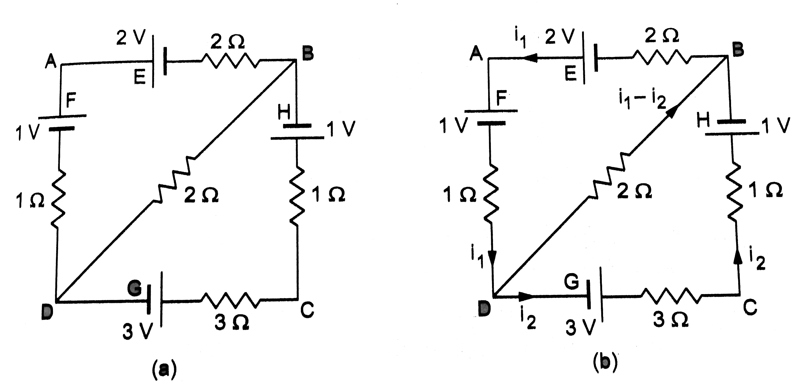
  6. In the circuit shown in figure E,F, G and H are cell of emf 2,1,3, and...

    Text Solution

    |

  7. Find the equivalent resistance between the point a and b of the circui...

    Text Solution

    |

  8. Find the currents going through the three resistors R(v),R(2)andR(3) i...

    Text Solution

    |

  9. Twelve wire, each having resistance r, are joined to form a cube as sh...

    Text Solution

    |

  10. Find the equivalent resistance of the circuit of the previous problen ...

    Text Solution

    |

  11. Find the equivalent resistance between thepoints a and b of the infini...

    Text Solution

    |

  12. Find the equivalent resistance of the network shown in figure between ...

    Text Solution

    |

  13. (a)Find the current I supplied by the battery in the network shown in ...

    Text Solution

    |

  14. A part of a circuit in steady state along with the currents flowing in...

    Text Solution

    |

  15. (a)find the potential drops across the two resistors shown in figure. ...

    Text Solution

    |

  16. A galvanometer has a coil of resistance 100(Omega) showing a full-scal...

    Text Solution

    |

  17. The electric field between the plates of a parallel-plate capacitor of...

    Text Solution

    |

  18. A capacitor is connected to a 12 V battery through a resistance of (10...

    Text Solution

    |

  19. A capacitor charged to 50 V is discharged by connecting the two plates...

    Text Solution

    |

  20. A 5.0(mu)F capacitor having a charge of (20 (mu)C)is discharged throug...

    Text Solution

    |