A
B
C
D
Text Solution
Verified by Experts
The correct Answer is:


Topper's Solved these Questions
SOLIDS & SEMICONDUCTOR DEVICES
MODERN PUBLICATION|Exercise Multiple Choice Questions - LEVEL -III (Questions From AIEEE/JEE Examination)|9 VideosSOLIDS & SEMICONDUCTOR DEVICES
MODERN PUBLICATION|Exercise Recent Competitive Questions|26 VideosSOLIDS & SEMICONDUCTOR DEVICES
MODERN PUBLICATION|Exercise Multiple Choice Questions - LEVEL -I (PARAGRAPH)|6 VideosROTATIONAL MOTION
MODERN PUBLICATION|Exercise RCQ|8 VideosTRANSFERENCE OF HEAT
MODERN PUBLICATION|Exercise Recent Competitive Questions|4 Videos
Similar Questions
Explore conceptually related problems
MODERN PUBLICATION-SOLIDS & SEMICONDUCTOR DEVICES-Multiple Choice Questions - LEVEL -II
- In the circuit , if the forward voltage drop for the diode is 0.5 V , ...
Text Solution
|
- A P - type semiconductor has acceptor level 57 meV above the valence b...
Text Solution
|
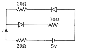
- Current in the circuit will be :
Text Solution
|
- The diode used in the circuit shown in figure has a constant voltage d...
Text Solution
|
- In the following common emitter configuration an NPN transistor with c...
Text Solution
|
- A sinusoidal voltage of Peak value 200 volt is connected to a diode an...
Text Solution
|
- The junction diode in the following circuit requires a minimum current...
Text Solution
|
- In the circuit given below , V(t) is the sinusoidal voltage source , v...
Text Solution
|
- Select outputs Y of the combination of gates shown below for inputs A ...
Text Solution
|
- In the following circuits PN - junction diodes D1,D2 and D3 are ideal ...
Text Solution
|
- Find V(AB)
Text Solution
|
- A diode is connected to 200 V (rms) ac in series with a capacitor as s...
Text Solution
|
- A potential difference of 2V is applied between the opposite faces of ...
Text Solution
|
- The contribution in the total current flowing through a semiconductor ...
Text Solution
|
- Ge and Si diode conduct at 0.3 V and 0.7respectively . In the followi...
Text Solution
|
- In the circuit shown in figure the maximum output voltage
Text Solution
|
- In the following circuit find I1 and I2
Text Solution
|
- The following configuration of gate is equivalent to :
Text Solution
|
- Figure gives a system of logic gates . From the study of truth table i...
Text Solution
|
- The combination of gates shown below produces
Text Solution
|